Euphonix System 5 Installation Guide System 5 Components
40
MC524 Monitor Interface
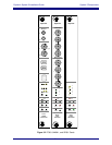
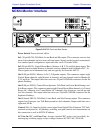
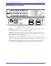
Figure 3-8 MC524 Front and Rear Panels
Power Switch: Powers the unit off/on.
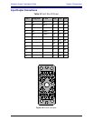
In 1 (38-pin ELCO): Talk Back, Listen Back and Mic inputs. This connector receives four
stereo listen channels and two stereo talk mic inputs. Signals can be boosted or attenuated.
In a standard patch configuration, input cable fans out to 12 female XLRs.
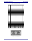
In 2 (90-pin ELCO): Control Room Buses, Monitor A, B, C, D, and Solo buses inputs. This
connector receives eight Monitor A channels, and two channels each for Monitor B, C, D.
These signals can be attenuated only and are typically fed from the AM713.
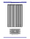
Out 1 (90-pin ELCO): Monitor A, B, C, D Speaker outputs. This connector outputs eight
Control Room channels, eight Monitor A channels, and two channels each for Monitor B,
C, D, and Solo. The output cable fans out to two 38-pin ELCO/Edak connectors for the Eu-
phonix Patchbay.
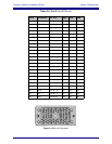
Out 2 (90 pin ELCO): Control Room Speakers, Talk Back and Listen Back Preamp, and
Solo Buses outputs. This connector outputs eight Control Room Main channels, six Control
Room Alt 1 channels, two Control Room Alt 2 channels, four Listen pre, two talk pre and
two Solo channels. The output cable fans out to two 38-pin ELCO/Edak connectors for the
Euphonix Patchbay.
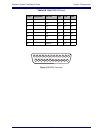
Out 3 (female DB-25): Talk Back, Listen Back, and Solo Preamp outputs. This connector
outputs four Listen pre, two Talk Back pre and two Solo channels. Output cable fans out to
eight male XLRs.
Control (DA-15): Input for digital control signal from Digital Pilot (Euphonix TCC bidi-
rectional serial protocol). All patching, switching, and gain controls are communicated via
this connection as well as MC524 IP address.
AC Line In (IEC) and Fuse Tray: Accepts standard IEC power cord (provided). An
autoranging switching supply accepts voltages between 90–250 VAC, 50–60 Hz.
MONITOR-COMMS INTERFACE
MC
524


