Euphonix System 5 Installation Guide System 5 Components
68
GP132
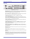
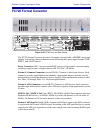
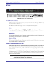
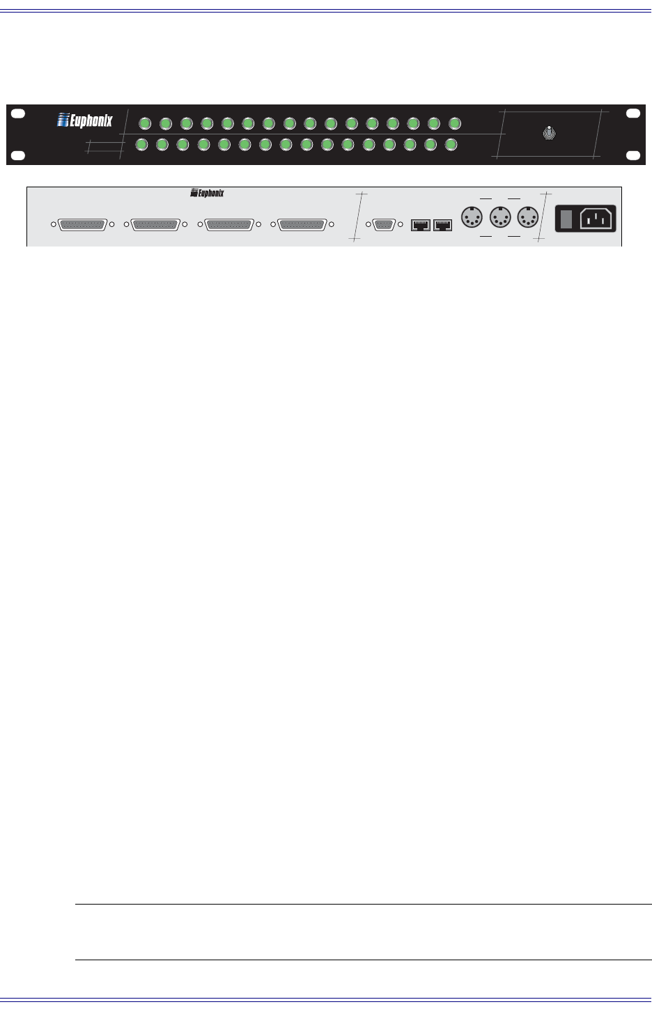
Figure 3-29 GP132 Front and Rear Panels
Front Panel Functions
While the toggle is in the Setup position, pressing button 16 clears all relays. Holding 14,
15, and 16 resets the GP132.
The GP132 has a three-state toggle switch on the right of the front panel:
Setup
For operation with Max Air, select 1-MIDI and 2-MMC on the front panel. All other se-
lections should be turned off except for 23-24T which remain on.
Relays Only
The front panel displays the state of the relays (outputs) and allows control of the relay clo-
sures manually from the buttons on the front panel.
Relays + Tallies
The front panel displays the state of the inputs and allows control of the relay closures man-
ually from the buttons on the front panel.
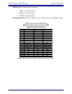
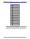
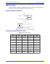
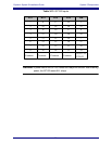
25-pin D-sub connectors RT1-RT4
Each connector has eight relay outputs and eight opto-isolated tally inputs. Since both out-
puts and inputs share common lines, you cannot use the same number connection for an
output and input simultaneously, and be careful when connecting multiple devices to the
same connector.
Tally inputs accept 5–24 VDC/AC. (Contact Euphonix Customer Service before applying
over 24 V.) The relays are rated at 500 mA maximum; an additional driver circuit is re-
quired to drain more current.
NOTE: The maximum length for any MIDI cable is 10 m. Cables over this length may
cause data loss (this is the MIDI specification).
AC I
NPUT
100
V
TO
260
V
50
TO
60 H
Z
MIDI
RS422 NET
O
UT
T
HRU
O
UT
T
HRU
I
N
I
N
O
I
S 1
S 1
S3
S3
S2
S2
GP132
RT1 1-8
RT1
RT2 9-16
RT2
RT3 17-24
RT3
RT4 25-32
RT4
GP132
1
Setup
Relays Only
Relays + Tallies
2 3 4 5 6 7 8 9 10 11 12 13 14 15 16
MIDI MMC N.O. C.C. SysX P2 EsBus EAddr Clear All
17 18 19 20 21 22 23 24 25 26 27 28 29 30 31 32
Net NAddr 24T 32T 48T 64T 96T S / R T: pulse T: -ve R: pulse R: NC


