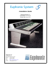
Euphonix System 5 Installation Guide
9
Chapter 1: System 5 Overview
This chapter explains the basic elements of any digital audio mixing system and introduces
the components of System 5. It concludes with a section explaining how to estimate your
system’s requirements.
Chapter 2: Interconnecting System Components illustrates how to connect the components,
where to locate them, and lists technical information about the components.
Chapter 3: System 5 Components presents relevant details about each component’s
connectors and cables.
Introduction to System 5
Digital Signal Processing (DSP)
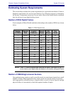
The DF64 Digital Frame is a rack-mounted unit that performs all audio processing in
System 5: dynamics and EQ, mix buses, record buses, aux sends, and monitor buses. Up to
four DF64s can be specified in a single system and their DSP can be allocated, using fac-
tory-supplied Mixer Model files, to provide different numbers of buses and channels for
each project. The number of DF64s required in a system depends on the number of logical
channels desired: a mono input uses one logical channel, a stereo input uses two, and a 7.1
input uses eight.
The System 5 Console
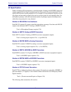
The System 5 console must contain the CM401 and CM402 center section modules and a
variable number of CM408 Eight-channel Modules, each providing eight physical faders.
Several optional sections can be included:
• CM403: Houses the dual joystick panner and film monitor panel;
• CM409F: Blank section the size of a CM408;
Facilities often install a larger console frame than is initially filled with modules
and panels. This can be due to plans for future expansion or to fulfill physical
requirements for console access. The blank sections merely fill in the space to
avoid having a hole across part of the console width;
• CM409H: Half-width blank section;
• CM409HTP: Half-width section that contains a trackball panner
The following sections discuss important concepts necessary to specify a console layout.


