


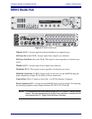
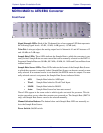

Euphonix System 5 Installation Guide System 5 Components
56
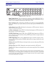
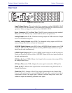
Manual Selection Buttons: The button below each Sample Rate LED row manually selects
the Sample Rate Source. The DM714 also allows manual selection of the Sample Rate.
Power Switch: On/Off switch.
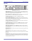
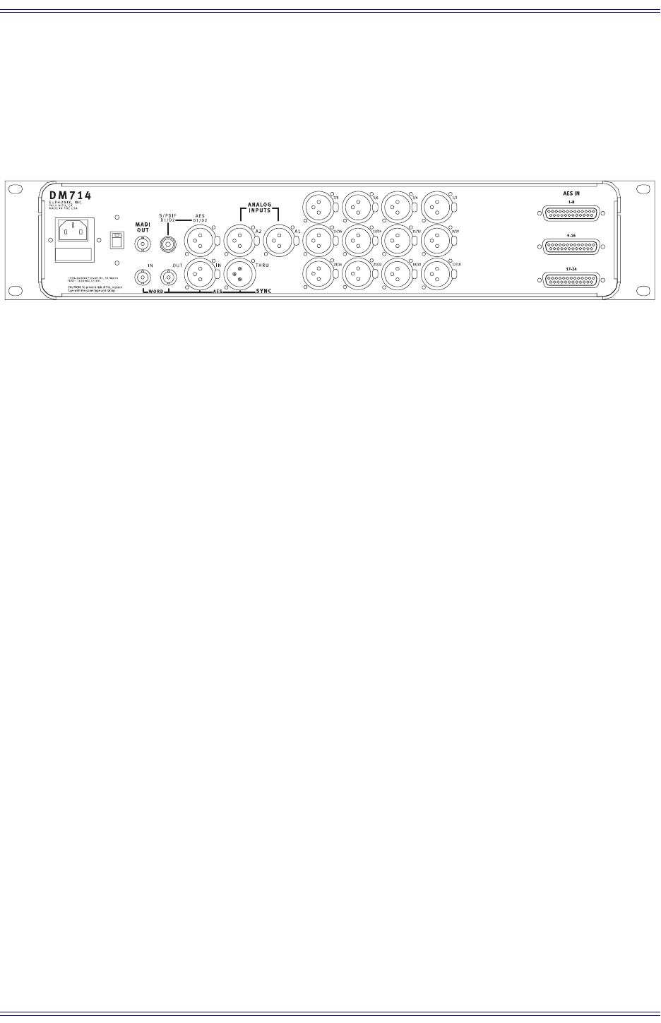
Rear Panel
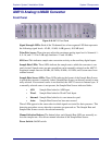
Figure 3-23 DM714 Rear Panel
Input Voltage Selector: This red switch allows operation in either 100/110/115 VAC or
220/230/240 VAC environments. A fuse must also be changed for 220/230/240 VAC op-
eration. Units are shipped set and fused for 100/110/115 VAC.
Power Connector (IEC) and Fuse Tray: The IEC power connector accepts standard IEC
power cords. The fuse tray contains both the active fuse and a spare for 220/230/240 VAC
operation.
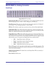
AES/EBU Digital Inputs (female XLR): 12 AES/EBU stereo inputs.
Parallel AES/EBU Digital Inputs (female DB-25): Three 8-channel digital connectors
function in parallel with XLR digital inputs, and should not be used simultaneously with
the XLR inputs. See Figure 3-24 on page 57 for pinout diagram.
Auxiliary Analog Inputs (female XLR): Two balanced analog inputs on XLR connectors.
Input sensitivity is set from the front panel.
Auxiliary AES/EBU Digital Input (female XLR): Stereo AES/EBU digital input on one
XLR connector. Functions in parallel with the auxiliary S/PDIF input and the two inputs
should not be used simultaneously.
Auxiliary S/PDIF Digital Input (RCA): Stereo S/PDIF digital input on one RCA connec-
tor. Functions in parallel with the auxiliary AES/EBU input and the two inputs should not
be used simultaneously.
AES Sync In (female XLR): Master clock input for the converter when using AES as Sam-
ple Rate Source.
AES Sync Thru (male XLR): Outputs the same signal connected to AES Sync In.
Word In (BNC): Master clock input for the converter when using Word Clock as Sample
Rate Source.