


Euphonix System 5 Installation Guide System 5 Components
49
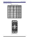
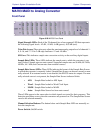
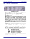
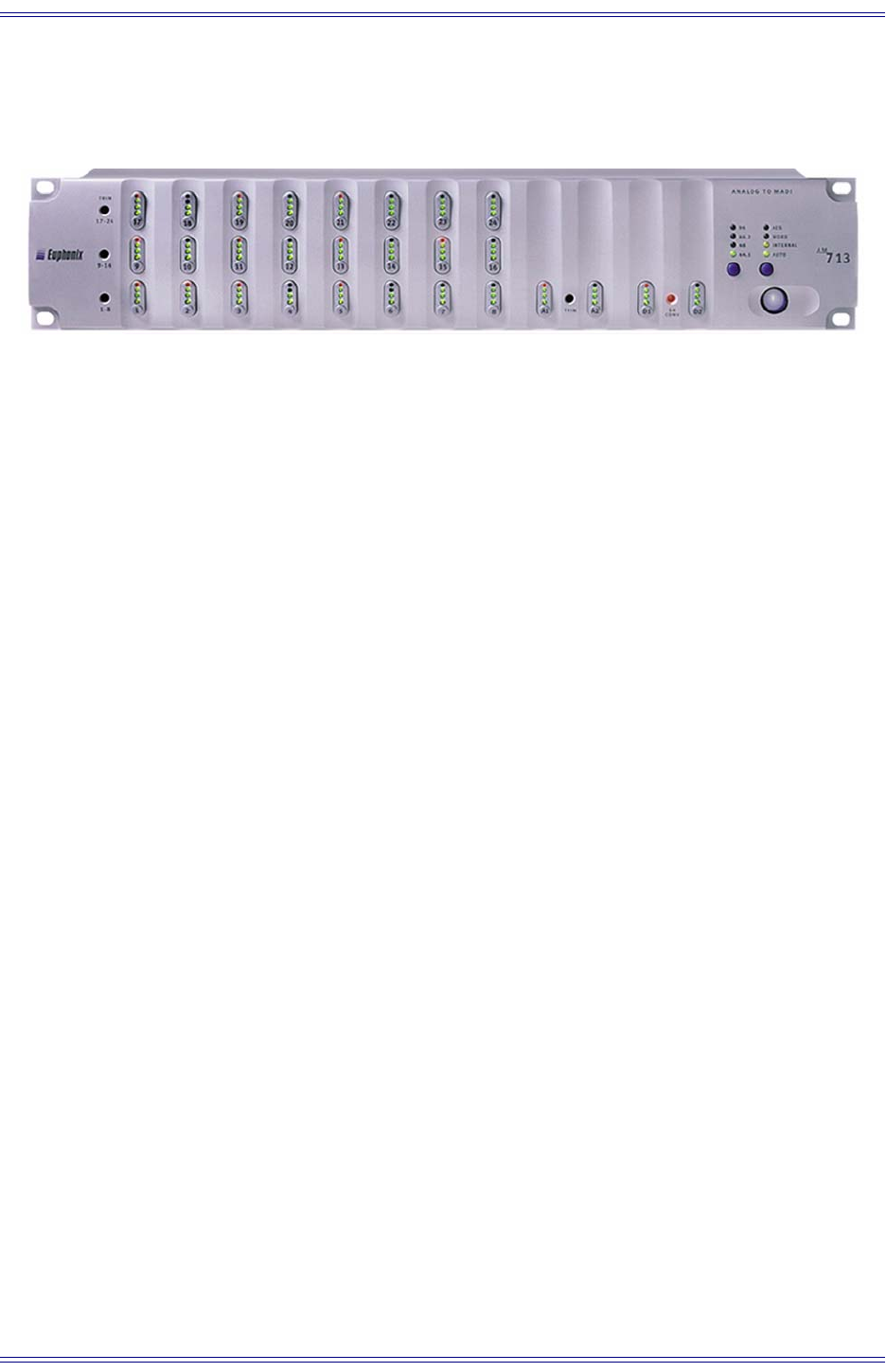
AM713 Analog to MADI Converter
Front Panel
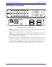
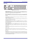
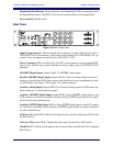
Figure 3-18 AM713 Front Panel
Signal Strength LEDs: Each of the 28 channels has a four-segment LED that represents
the following signal levels: -42 dB, -18 dB, -6 dB (green), -0.05 dB (red).
Trim Pots Access: Three trim pots adjust the maximum analog input level of channels 1–
8, 9–16, and 17–24 in 2-dB steps between +12 and +26 dBu.
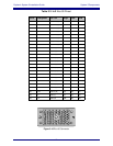
SR Conv: This indicates sample-rate conversion activity on the auxiliary digital inputs.
Sample Rate LEDs: These LEDs indicate the sample rate to which the converter is cur-
rently locked. Sample rates are auto-sensed but can be manually selected on the AM713.
Supported sample rates are 96 kHz, 88.2 kHz, 48 kHz, 44.1 kHz, and Custom rates from
external sources.
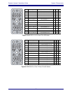
Sample Rate Source LEDs: These LEDs indicate the format of the Sample Rate Source
to which the converter is currently locked. Sample Rate Source can be auto-sensed or man-
ually selected. If an external source is not detected, the AM713 reverts to Internal sync. If
a manually selected source is not present, the Sample Rate Source indicator blinks.
• AES: Sample Rate locked to AES Input.
• Word: Sample Rate locked to Word Clock Input.
• Internal: Sample Rate locked to its own internal crystal.
• Auto: Sample Rate Source has been auto-sensed.
These LEDs appear in the same order in which signals are tested for their presence. This
detection procedure occurs when the converters are powered on. The Sample Rate and
Sample Rate Source can also be selected manually.
Manual Selection Buttons: The button below each Sample Rate LED row manually se-
lects the sample rate. Also allows manual selection of the Sample Rate Source.
Power Switch: On/Off switch.