


13
If you select another program or turn the power off before you write, your edits
will be lost.
If the parameter value does not change when you turn knobs 1–5
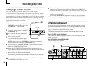
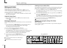
When you use EDIT SELECT 1 or EDIT SELECT 2 to select a section and turn
knobs 1–5 to edit the parameter values, the value in the display will sometimes
continue blinking, and the parameter value will not change.
This occurs when there is a discrepancy between the actual value of the
parameter being edited (the value that is blinking in the display) and the
position of the knob. If the actual value is significantly different from the
position of the knob, and the value changed immediately when you moved the
knob, the sound would change in a sudden and unnatural way.
To prevent this from happening, the knob and parameter will begin changing in
tandem only when the knob position corresponds to the actual value of the
edited parameter (the value in the display will stop blinking).
For example, suppose that you turn knob 1 to edit a parameter,
so that the knob is in the position shown at left.
Then you use the EDIT SELECT 1 knob to switch to a different
parameter section, and want to edit the parameter assigned to
knob 1. The actual value of this parameter is at the position of
the triangle in the diagram at left. (The actual value will blink
when you turn the knob slightly.) The parameter value will not
change until you turn the knob all the way to that position.
When the knob reaches the position of the actual value, the knob
and parameter value will begin changing in tandem, so that you
can edit the value. (When the knob reaches the actual value, the
value in the display will stop blinking.)
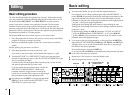
To return to the original parameter values of a program
The edit control ORIGINAL VALUE LED will light to indicate the parameter
values of a preset program or a program that you saved.
If you want to return parameters to their original values, turn knobs 1–5 so that
the ORIGINAL VALUE LED is lit.
If you select another program or re-select the same program while you are
editing, all parameters will return to the values of the preset program or the
previously-saved program.
In the same way as when editing a program, you can make settings for the
entire microKORG or MIDI-related settings by selecting the desired parameter
section and turning knobs 1–5 to make the settings (➝p.47, 51). Changes you
make to these settings will also be lost if you turn the power off, so you must
Write them if you want to keep your changes.
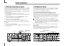
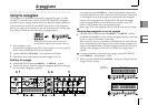
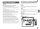
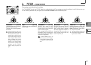
How to read the pages for each section (➝p.16–)
24
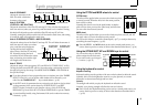
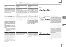
CUTOFF [0...127]
Sets the cutoff frequency.
Increasing this value will raise the
cutoff frequency.
"CUTOFF" can be varied by
time-variant change produced
by Filter EG, by keyboard play-
ing dynamics (velocity), and by
note location (keyboard track-
ing).
If the "CUTOFF" value is low-
ered, the volume may be ex-
tremely low, or you may hear no
sound at all.
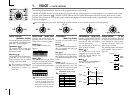
RESONANCE [0...127]
Sets the resonance of the filter.
This will emphasize the overtones
near the cutoff frequency specified
by "Cutoff," adding a distinctive
character to the sound. Increasing
this value will increase the effect.
(➝Figure 6-4)
Since movement of the "CUTOFF"
knob will affect the overtones that
are boosted by resonance, it is best
to adjust "CUTOFF" and "RESO-
NANCE" in conjunction with each
other.
TYPE [-24dB LPF, -12dB LPF,
-12dB BPF, -12dB HPF]
Selects the type of filter
24dB LPF ( ):
The -24 dB LPF (-24 dB/octave Low
Pass Filter) is the most common
type of filter; it passes the frequen-
cies that are below the cutoff fre-
quency, and cuts the frequencies
that are above (➝Figure 6-1). Low-
ering the cutoff frequency will
make the tone darker and more
mellow.
-12dB LPF ( ):
The -12 dB LPF (-12 dB/octave Low
Pass Filter) has a more gentle slope
than the -24 dB LPF, producing a
more natural-sounding effect.
(➝"-24 dB LPF")(➝Figure 6-1)
Figure 6-1
LPF (Low Pass Filter)
-12dB/oct
-24dB/oct
Cutoff
Frequency
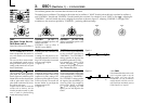
6. FILTER
— SYNTH
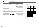
FILTER EG INT [-63...63]
This specifies how time-variant
modulation from the Filter EG will
be applied to the cutoff frequency
(➝Figure 6-5). The cutoff frequency
will change over time according to
the Filter EG settings, modifying
the tone. For example, you can use
this to create a sound that gradu-
ally begins to brighten when you
press the key, and then gradually
becomes darker.
This INT (Intensity) parameter
specifies the depth (sensitivity) to
which the Filter EG will affect the
cutoff frequency.
With a setting of 0, the Filter EG will
not affect the cutoff frequency. In-
creasingly positive (+) settings will
allow the Filter EG to have a corre-
spondingly greater effect on the
cutoff frequency. (➝Figure 6-6)
Increasingly negative (-) settings
will allow a correspondingly
greater effect in the opposite direc-
tion. (➝Figure 6-7)
FILTER KEY TRACK [-63...63]
This specifies how keyboard track-
ing (the keyboard location that you
play) will affect the cutoff fre-
quency.
For example if the sound played by
the C4 key has the desired tone but
higher notes no longer have reso-
nance or are too mellow-sounding,
you can adjust keyboard tracking to
make compensations so that the
cutoff frequency will rise for higher
notes.
With positive (+) settings, the cut-
off frequency will rise as you play
upward from the C4 note, and fall
as you play downward. With nega-
tive (-) settings, the cutoff frequency
will fall as you play upward from
the C4 note, and rise as you play
downward.
With a setting of +48, the change
in cutoff frequency will be pro-
portionate to the change in
pitch. With a setting of 0, key-
board tracking will not affect the
cutoff frequency.
The filter removes unwanted frequency regions of the sound produced by the oscillator. It determines the tone by allowing only the desired
portion of the sound to pass. "TYPE" (knob 1) selects the type of filter (i.e., the way in which it will cut the frequency). "CUTOFF" (knob 2) sets
the frequency at which the cut will occur. Normally, turning this knob toward the right will brighten the sound, and turning it toward the left
will darken the sound. "RESONANCE" (knob 3) emphasizes the frequency region near the cutoff frequency, adding a distinctive character to
the sound. Other parameters in this section let you specify the depth of the modulation applied by the filter EG, and the way in which keyboard
tracking will affect the cutoff frequency.
Figure 6-4
LPF
HPF
BPF
The effect of resonance
Low resonance value
High resonance value
This indicates the position of
the EDIT SELECT 1/2 knob.
The EDIT SELECT 1/2 knob
selects the section that will be
edited. In this example, the
FILTER section is selected.
These are the edit control knobs
1—5. The markings printed
around each knob are the
values that will be selected
when you turn that knob. These
positions are approximate.
This area lists the parameters
that are edited by edit control
knobs 1—5 when the above
section is selected. The range of
values for each parameter is
given in square brackets [ ].
Explanations of each parameter
and its values are given below.
This is the name of the section.
When you have set the EDIT
SELECT 1 or 2 knob to the
FILTER position and would like
to see an explanation of the
parameters, refer to this page.
A summary of this section
is given here.
This section applies to
synth programs.
Basic editing