


38
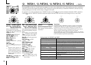
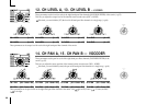
CH 1 LEVEL [0...127] CH 2 LEVEL [0...127] CH 3 LEVEL [0...127]
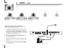
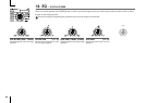
12. CH LEVEL A, 13. CH LEVEL B — VOCODER
These parameters set the level for each of the eight band-pass filter channels (SYNTHESIS FILTER) of the carrier (➝p.35).
This lets you adjust the output level of the internal carrier sound source (OSC 1, NOISE).
If desired, you can initialize (127) the level of all band-pass filter channels in a single step. (➝p.60)
CH 5 LEVEL [0...127] CH 6 LEVEL [0...127] CH 7 LEVEL [0...127]
CH 4 LEVEL [0...127]
CH 8 LEVEL [0...127]
These parameters set the output level for each of the eight band-pass filter channels of the carrier.
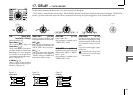
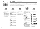
CH 2 PAN [L63...Center...R63] CH 3 PAN [L63...Center...R63]CH 1 PAN [L63...Center...R63] CH 4 PAN [L63...Center...R63]
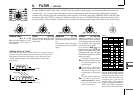
14. CH PAN A, 15. CH PAN B — VOCODER
These parameters set the pan for each of the eight band-pass filter channels (SYNTHESIS FILTER) of the
carrier (➝p.35).
This lets you adjust the stereo position of the internal carrier sound source (OSC 1, NOISE).
If desired, you can initialize (center) the pan of all band-pass filter channels in a single step. (➝p.60)
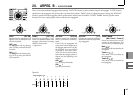
CH 5 PAN [L63...Center...R63] CH 6 PAN [L63...Center...R63] CH 7 PAN [L63...Center...R63] CH 8 PAN [L63...Center...R63]
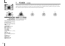
These parameters set the pan for each of the eight band-pass filter channels of the carrier. L63 ( ) is far left, Center ( ) is center, and R63
(
) is far right.