


34
5. MIXER — VOCODER
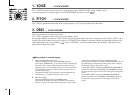
OSC 1 LEVEL [0...127]
Specifies the output level of Oscil-
lator 1 (carrier).
INST LEVEL [0...127]
Specifies the output level of the sig-
nal that is input from AUDIO IN 2.
NOISE LEVEL [0...127]
Specifies the output level of the
noise generator.
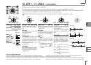
This sets the output level of the carrier. The level you specify here will be the input level to the band-pass filter (Synthesis Filter) of the
carrier.
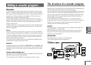
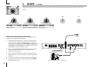
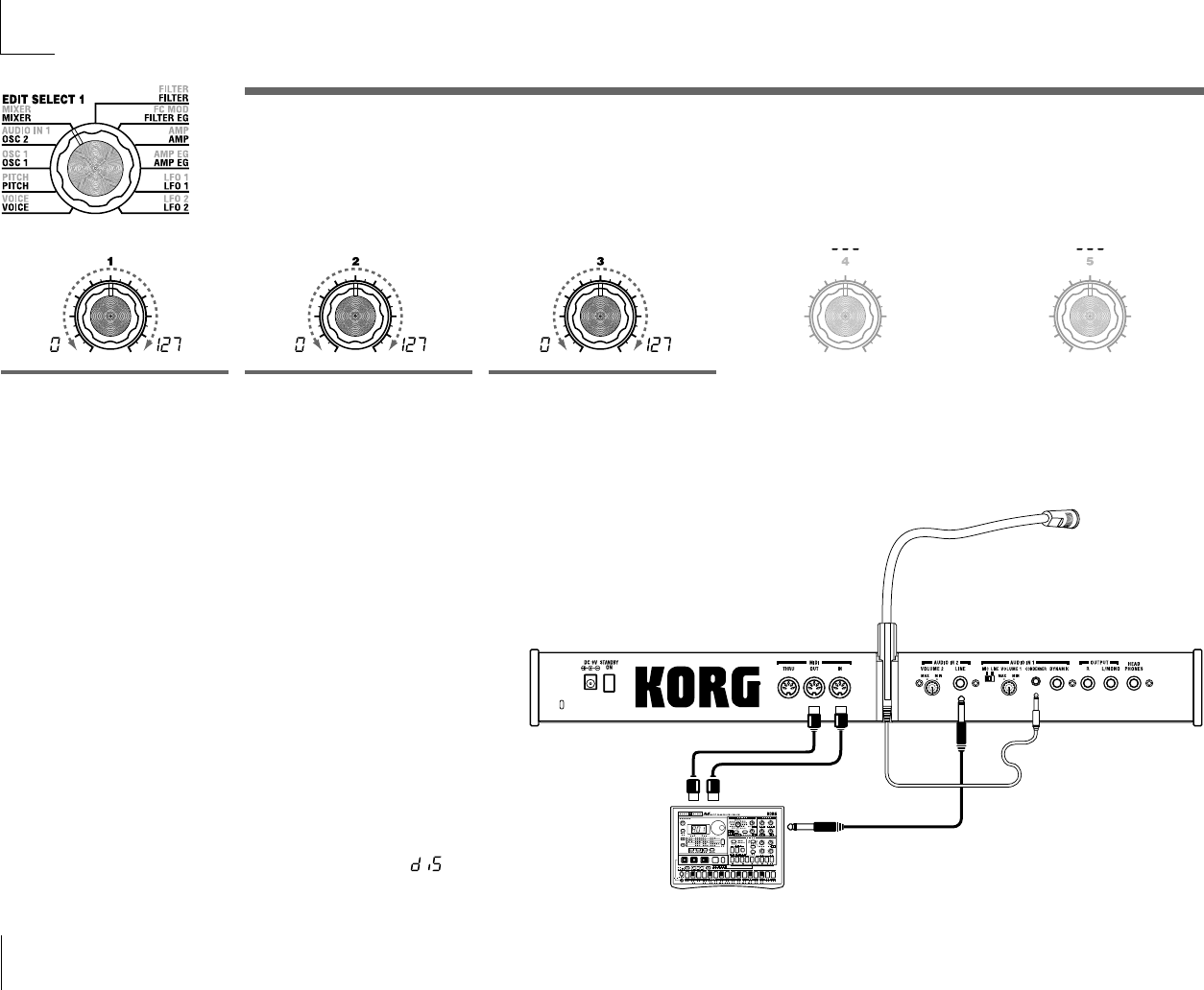
Using an external input as the carrier of the vocoder
Here's how to use a signal input from the AUDIO IN 2 LINE jack as the
vocoder carrier (the signal that is modulated).
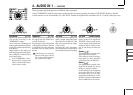
1
As described in the connections for "1. Playing a vocoder program"
and "Processing an external input signal" (➝p.10, 21), connect the
included mic to the AUDIO IN 1 CONDENSER jack, and connect the
output jack of your external device to the AUDIO IN 2 LINE jack. Use
the VOLUME 1 and VOLUME 2 knobs to adjust the levels so that the
audio signals are output to AUDIO IN 1 and 2.
2
When you raise the MIXER "INST LEVEL" (knob 2) value, the input
signal from AUDIO IN 2 will be input to the band pass filter
(synthesis filter) of the carrier.
3
When you raise the MIXER "OSC 1 LEVEL" (knob 1) and play the
keyboard, the OSC 1 waveform will be input to the band pass filter of
the carrier.
4
If you set the AUDIO IN 1 "HPF GATE" (knob 4) to Disable ( ),
the high-frequency portion of the input signal from the AUDIO IN 1
jack will always be output.
MIDI IN
MIDI OUT
MIDI keyboard, tone generator module, rhythm machine etc.
EM-1
TAP
1 2
5
7
10 12
14
16
15131198
4
3
Included mic