


32
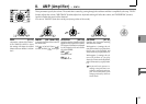
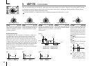
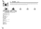
1. VOICE — SYNTH/VOCODER
The "1. VOICE" parameters are the same as for a synth program with a "SINGLE/LAYER" setting of Single (➝p.16).
To use the program as a vocoder program, set "SYNTH/VOCODER" (knob 1) to Vocoder (
)).
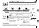
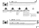
2. PITCH — SYNTH/VOCODER
The "2. PITCH" parameters are the same as for a synth program (➝p.17). They specify the pitch of the carrier.
3. OSC1 — SYNTH/VOCODER
Here you can select the waveform of the carrier.
The "3. OSC1" parameters are the same as for a synth program (➝p.18).
By selecting a different waveform for "WAVE" (knob 1) you can change the depth of the effect. Normally, you will set OSC 1 "WAVE" to be a
triangle wave which contains a rich set of overtones, or VOX WAVE which simulates a waveform similar to that produced by human vocal
cords. Alternatively, you can select DWGS (
), and use "CONTROL 2" to select waveform number 26 (5th Wave3: a fifth interval), and
play a chord to obtain rich sounds.
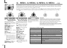
Editing example for a vocoder program
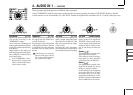
1
Adjust the audio from the mic input.
Turn the EDIT SELECT 1 knob to the AUDIO IN 1 position.
Turn knob 2 ("THRESHOLD"). As you turn the knob toward the right,
the sound will be cut more readily. Adjust this so that noise is not
obtrusive when you are not speaking into the mic. Then adjust knob 1
("GATE SENSE") so that the vocoder sound that is output is not cut
off in an unnatural way.
Turning knob 4 ("HPF GATE") toward the right will emphasize the
consonants (e.g., "s" sounds) of the input voice. (➝p.33)
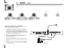
2
Make filter settings.
Turn the EDIT SELECT 1 knob to the FILTER position.
Turn knob 4 ("EF SENSE") to adjust the sensitivity of the envelope
follower. As you turn the knob toward the right, the vocoder output
will rise more smoothly, and the release will become longer.
Turning knob 2 ("CUTOFF") or knob 1 ("FORMANT SHIFT") will vary
the cutoff frequency of the band pass filter for the carrier, changing
the character of the vocoder output. (➝p.35)
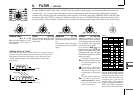
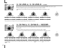
Turn the EDIT SELECT 2 knob to the CH LEVEL A or CH LEVEL B
position. Turn knobs 1–4 for CH LEVEL A or CH LEVEL B to adjust
the band pass filter output levels for each of the eight channels of the
carrier.
Turn the EDIT SELECT 2 knob to the CH PAN A or CH PAN B
position. Turn knobs 1–4 for CH PAN A or CH PAN B to adjust the
band pass filter output pan for each of the eight channels of the
carrier.