


17
Owner’s Manual
Owner’s Manual
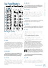
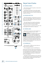
41. AUX RETURN
This adjusts the processed signal level coming in from
your external effects processor via the aux return [9]
jacks. Use it to adjust the returned signal level going
onto the main mix bus.
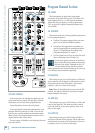
4. CROSSFADER CONTOUR
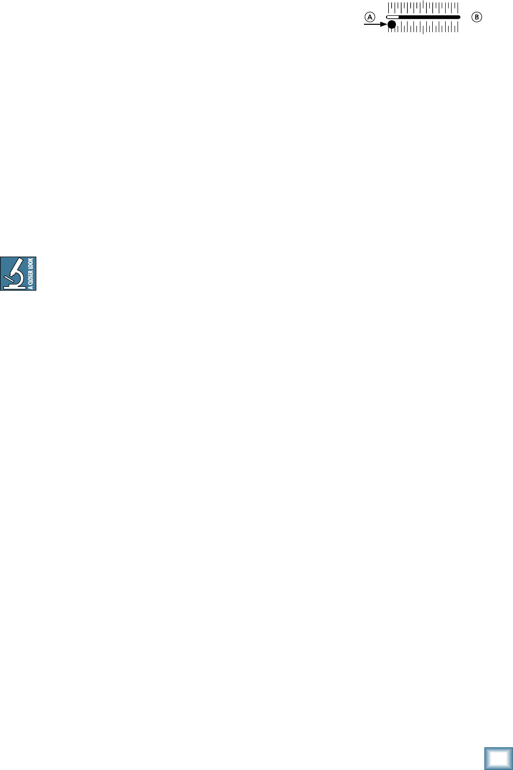
Use this to adjust how fast or slow the crossfader [43]
responds to movement.
In the slow position, the crossfader responds in a
linear fashion, increasing from A to B at the same rate
across its length of travel.
In the fast position, the crossfader responds logarith-
mically, increasing from A to B very quickly, and then
changing very little for the remainder of the fader’s
travel.
In the fast position, crossfading occurs within
the first 5 mm of luxurious fader travel. This
is useful for cutting, where you can mix a
scratch over existing program material. In
this style, you can keep the fader either at the complete
edge of the fader’s travel, or only a very small amount
from that, and a very steep fade slope is desired. Then
you can quickly “crab” the fader to cut the scratch signal
into the program signal.
Adjust the control between the two extremes to get
the crossfader response that works best for your style.
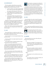
4. CROSSFADER
The signal level of programs assigned to A or B by
their program assign [37] switches will be affected by
the position of the crossfader.
This crossfader is a high-quality infinium
™
contact-
free optical digital fader, designed to last the lifetime of
the d.4 Pro with no degradation in quality.
The sensitivity of the travel can be adjusted using the
crossfader contour [42] control.
You can also adjust the tension of the crossfader
movement to suit your delicate taste, by following these
steps:
1. Turn off the AC power, and remove the AC
power cord.
2. Mov
e the crossfader all the way to the left.
3. Re
move the fader cap (knob) by grasping it
firmly and pulling it straight up.
4. Use a small slot
-head screwdriver to turn the
screw located through the hole on the left
side of the crossfader slot. You might need a
flashlight to make sure you are lined up on the
screw. Rotate the
screw clockwise
to tighten the ten-
sion, or counter-
clockwise to loosen.
5. Replace the fader cap, and you’re al
l done.
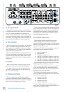
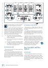
44. FILTER TYPE
Each program has a filter [34] switch that allows you
to choose if the program goes through a filter (X or Y)
before the program is added to the main mix.
This 4-position rotary switch allows you to choose the
filter type, or bypass it:
• HP (high-pass): Frequencies below the
filter
frequency setting are attenuated.
• BP (band-pass): Frequencies either side
of the
filter frequency setting are attenuated.
• LP (low-pass):
Frequencies above the filter
frequency setting are attenuated.
• BYP (bypass): No filter is inserted into the
signal
45. FILTER RESONANCE
This control will boost the filter’s resonance to provide
up to 15 dB of boost at the filter frequency. The filter has
a gradually narrowing Q as resonance increases.
4. FILTER FREQUENCY
This allows you to adjust the filter’s frequency, with a
range between 40 Hz and 16 kHz.
For example, if you want a filter that drops off the
lows below 80 Hz, select the filter type to be high-pass,
and adjust the frequency to 80 Hz.
You might find it fun to set the resonance, then rotate
the frequency while using the bump switch (see below)
to cut the filter in and out. The filter controls are posi-
tioned closely to allow this easy kind of DJ play.
47. FILTER TOGGLE
This switch selects one of three possible positions:
On: The filter is engaged.
Bypass: The filter is bypassed and has no effect on
the audio.
Bump: This spring-loaded momentary position
allows you to quickly engage or disengage the
filter.