


p.133
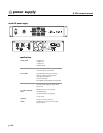
Group section: Compressor/Limiter functions
The gate and compressor functions affect all signals summed into their respective Audio Group
buses. Also, since the Audio Group external inputs are located pre-dynamics, the
compressor/limiter and gate functions also can be used to control dynamics of an external sig-
nal (e.g. separate submixer).
To set up the compressor/limiter function:
1. If desired, link adjacent odd and even channels for stereo operation - Pressing the STEREO
LINK switch links the two channels for stereo operation. The channel with the highest amount
of attenuation becomes the controlling channel for both channels of the stereo pair. This
ensures that the stereo signal tracks evenly in the final stereo mix. The LED lights to indicate
stereo link is active.
NOTE:You may use the stereo link function to key operation of one channel by the signal of
the paired channel. To do this, first set the controlled channel Ratio to 1:1 and Threshold to 0
or above. Then, set the controlling channel Threshold and Ratio controls to achieve the desired
compression effect on the controlled channel.
2. Select compressor mode (VOX, PERC or AUTO) - Selecting either or both switches turns
the Compressor system on.The ON/THR LED will light to indicate compressor function is
active. Press VOX for attack and release times optimized for vocals (slow averaging). Press
PERC for attack and release times optimized for percussion (fast averaging). Press both for
AUTO mode (attack and release times are determined by signal characteristics).
3. Select Hard or Soft Knee - Pressing this switch down sets the compressor for a Soft Knee
characteristic. When the threshold level is reached,the onset of compression is gradual, with
the ratio increased "softly" until the set ratio is reached. Soft Knee compression tends to be
more forgiving and "musical." When the switch is up, the compressor/limiter exhibits a "hard
knee" characteristic.When input signals reach the threshold,output is immediately reduced by
the set ratio. This characteristic is best employed for overload protection using higher thresh-
old settings.
4. Set compressor/limiter threshold - Set the COMP THR control to the input signal level
where you wish compressor action take effect.Any signal level above this setting will cause a
reduction in output signal as determined by the RATIO setting.The dual color ON/THR LED
lights red when the signal surpasses set threshold level.
5. Set compressor/limiter ratio - Set the COMP RATIO control to determine the desired
amount of proportional amount gain reduction to occur whenever the input signal exceeds the
threshold setting. Ratio is adjustable from 1:1 to 20:1 (hard limiting).
6. Set compressor make-up gain - This control adjusts to make up for apparent loss of gain due
to compression of the input signals.To view the output of the post-dynamics Audio Group,
select SOLO in the pre-fader (default) mode.This shows the output level following dynamics
control and before any effects of the VCA control system (if engaged for this Audio Group).
The COMP GAIN control should be adjusted to show close to 0dB reference level when nor-
mal signals are present. The GAIN control has a range of 0dB to +20dB.
Once set-up is complete, the effects of compressor/limiter action can be viewed on the ATT
gain reduction meter. This meter shows overall reduction applied by the dynamics system.
NOTE:When the gate function also is engaged,the meter displays attenuation applied by both
the compressor and gate functions.However,in most applications, only one function will be
active at any given moment. Active function is indicated by red illumination of either the com-
pressor ON/THR LED or the gate ON/THR LED.
Caution should be exercised in operation of the dynamics system if the ATT meter displays frequent or constant full-
scale deflections.
9
dynamics control