


Note: Caution should
be exercised if a sig-
nificant amount of gain
reduction is displayed, as
this may cause a deteriora-
tion in overall sound quality.
+
EXTREME CAUTION should
be observed when removing
or turning off any limiter.
Depending on level settings
and how much limiting is
taking plase, an abrupt level
change can take place
that could startle listeners
and even damage speak-
ers.
a
4
p.65
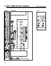
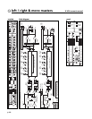
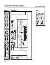
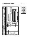
left / right & mono master modules
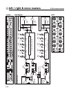
output limiter features
The L/R and Mono outputs are equipped with independent output limiters.
The limiters are located AFTER the console output faders and only affect
the signals that appear at the main Left, Right and Mono XLR's.
Limiting takes place according to the RMS level, allowing short term signal
peaks to pass without attenuation. Limiters may be used for speaker pro-
tection, or to prevent the system from producing sound levels that exceed
local noise ordinances.The Left and Right signals are processed together by
the Left / Right limiter (located above the Left / Right master faders) and
the Mono signal is processed by the Mono limiter (located above the Mono
master fader).
The features for both the Stereo and Mono limiters are identical.
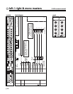
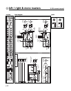
output limiter threshold control
Adjusts the limit point.Any signal level beyond this point will cause
attenuation at a ratio of 20:1. The limiter circuit provides "soft knee" limit-
ing.This means that when a signal approaches the limit point, a certain
amount of dynamic compression is applied in order to soften the effects of
the limiter. Hard limiting occurs when the incoming signal is continuously
above the limiter threshold.The threshold is adjustable from -6 to +20 dBu.
output limiter on switch
Activates the output limiter.When activated, the LED at the top of the
Gain Reduction meter is alluminated.
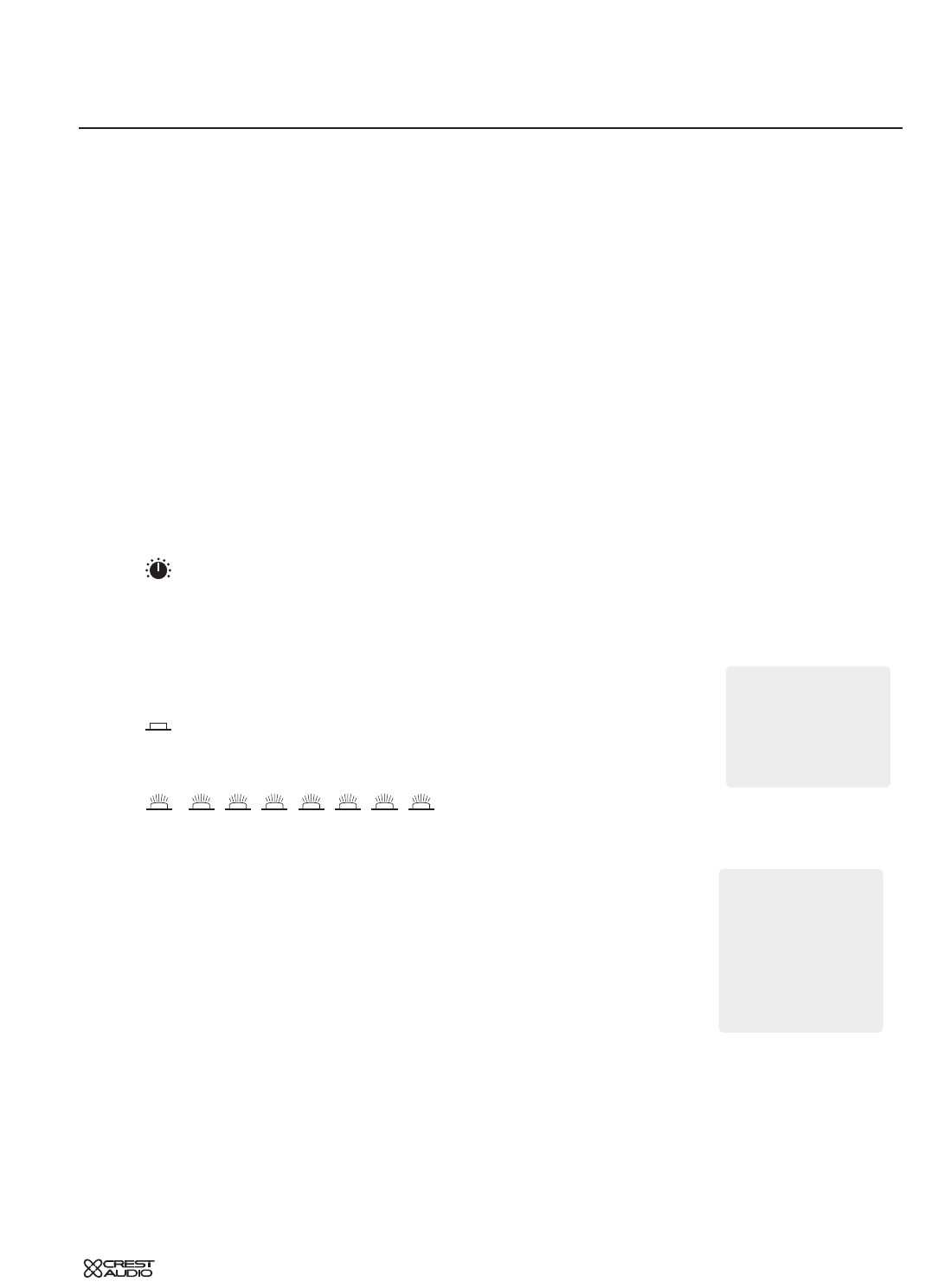
gain reduction metering
This eight segment meter indicates
how much limiting, or signal attenuation is taking place. Since the meter is
showing attenuation, the LED's illuminate downward, and not upward as
one would expect with a level increase.The range displayed by the gain
reduction meter is between 1 and 24 dB of attenuation. The top LED illu-
mininates when the Output Limiter is on.The other seven LED's respond to
signal attenuation.
For more information, see the section on Gates, compressors and limiters.
LEDLEDLEDLEDLEDLEDLEDLED