SRP-X500P RS-232C Interface Manual
♦ LINE TRIM (43rd byte)
Shows the setting of the TRIM controls for the LINE input on the front panel of the SRP-X500P (in
dBu units).
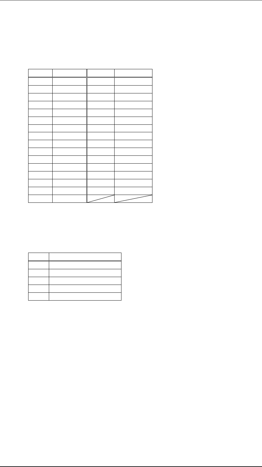
The parameter and the TRIM control setting are shown in the following table.
TRIM TRIM
-30 0x30 (‘0’) -14 0x40 (‘@’)
-29 0x31 (‘1’) -13 0x41 (‘A’)
-28 0x32 (‘2’) -12 0x42 (‘B’)
-27 0x33 (‘3’) -11 0x43 (‘C’)
-26 0x34 (‘4’) -10 0x44 (‘D’)
-25 0x35 (‘5’) -9 0x45 (‘E’)
-24 0x36 (‘6’) -8 0x46 (‘F’)
-23 0x37 (‘7’) -7 0x47 (‘G’)
-22 0x38 (‘8’) -6 0x48 (‘H’)
-21 0x39 (‘9’) -5 0x49 (‘I’)
-20 0x3A (‘:’) -4 0x4A (‘J’)
-19 0x3B (‘;’) -3 0x4B (‘K’)
-18 0x3C (‘<‘) -2 0x4C (‘L’)
-17 0x3D (‘=‘) -1 0x4D (‘M’)
-16 0x3E (‘>‘) 0 0x4E (‘N’)
-15 0x3F (‘?’)
♦ AV/RGB TRIM (44th-48th byte)
Shows the setting of the TRIM controls for the AV/RGB input on the front panel of the SRP-X500P (in
dBu units).
The AV/RGB TRIM parameter consists of the 5 bytes of data in the order shown in the following table.
Byte Parameter
1st AV/RGB INPUT A TRIM
2nd AV/RGB INPUT B TRIM
3rd AV/RGB INPUT C TRIM
4th AV/RGB INPUT D TRIM
5th AV/RGB INPUT E TRIM
The correspondence of the parameter with the TRIM control settings is the same as that of the LINE
TRIM parameter.
♦ REF INDICATOR (49th byte)
Shows the status of the REF. indicators on the front panel of the SRP-X500P in the form of 8 bits of
data.
The bit is 0 for indicators that are turned off and 1 for indicators that are turned on.
MSB LSB
bit7 bit6 bit5 bit4 bit3 bit2 bit1 bit0
0 1 AV/RGB LINE MIC 4 MIC 3 MIC 2 MIC 1
/WL 2 /WL 1
Page 30/43


