


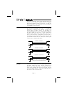

channel path (see section 9) the insert is after that sec-
tion, allowing equalisation of both the insert send and
return. The signal from the channel appears on the TIP
of the plug and is returned on the RING. The insert
point allows limiters, compressors and other signal
processing units to be added as required to particular
input channels.
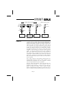
4. LINE INPUT
The LINE Input is a
1
⁄
4
" 3 pole Agauge jack socket, to
accept balanced or unbalanced line level sources when
the LINE switch(5) is pressed. Unlike the low imped-
ance Microphone input, this stage presents a high
impedance(>10kΩ) to the input signal, enabling many
types of instruments to be plugged straight in without
D.I. boxes or external preamplifiers.
Line inputs will be useful as extra Effects Returns,
where additional post-effect equalisation is required.
5. LINE SELECT
The LINE switch selects Line input when pressed, and
Microphone input when released. When Line is se-
lected the Gain range is reduced by 20dB(see 6 below).
6. GAIN CONTROL
When the Microphone input is selected this control acts
as a SENSITIVITY control covering a 50dB range. Chan-
nel signal level increases as the control is turned
clockwise. When the Line input is selected it serves as
a GAIN control, with the scaling reduced by -20dB from
the printed scale. There is a line-up mark at the Line in-
put unity gain point. Some audio equipment,
particularly that intended for domestic use, operates at
a nominal -10dBV level and an increased Gain setting
will be required.
7. CHANNEL/MONITOR INPUT REVERSE
Normally the input to the Channel is the Mic/Line
source, while the input to the Monitor path is the tape
return. The CHANMNTR INPUT REV switch swaps over
these inputs, allowing the tape return signal to be
brought down the full facilities of the Channel path dur-
Page 11