


from the main outputs and can therefore provide addi-
tional outputs for foldback or external processing units.
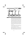
The six Auxiliary busses are arranged in two sections
of three, with each section comprising a pre-fade Fold-
back (FB) send and two post-fade, post-cut switch
auxiliary sends. Normally FB1 and AUX 1 & 2 are in
the Channel path, while FB2 and AUX 3 & 4 are in the
Monitor path.
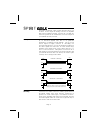
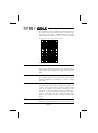
13. CHANNEL PAN
The Pan control determines the position of the Channel
signal within the stereo image. Rotation fully anticlock-
wise feeds the signal solely to the Left mix buss and
odd-numbered Groups, while rotation clockwise
sweeps the image to the Right and even-numbered
Groups.
14. CHANNEL PFL/PEAK LED
When the PFL switch is pressed, the Pre-Fade signal is
fed to the Control Room and headphones outputs,
where it replaces the selected source. The PFL/AFL
LED on the master section illuminates to warn that the
monitor and the meters are now responding to the
PFL/AFL selection and the PFL LED on the input chan-
nel lights to identify the active channel. This is a useful
way of listening to any required input signal without in-
terrupting the main mix, so that adjustments can be
made or problems traced.
When the PFL switch is released the LED on the chan-
nel serves as a PEAK indicator, to warn when an
excessively high signal level is present in the channel.
The signal is sampled at two points in the channel,
PRE INSERT, (PRE HF/LF EQ if in the Channel path),
and POST EQ. The Peak LED will illuminate approxi-
mately 4dB before clipping and therefore give warning
of a possible overload even if the peaks are removed
by external equipment plugged into the Insert.
15. CHANNEL ON
This switch routes the Channel signal to the Channel
PAN control and then to the routing matrix. It is posi-
tioned post-fader to ensure minimum system noise
when released, while leaving the pre- fade foldback
sends enabled.
Page 14