The bargraphs may be calibrated by trimmers fitted on
the edge of the PCBs and accessed via holes in the
panel above each meter. Adjustments may be made
using a small screwdriver, taking care not to damage
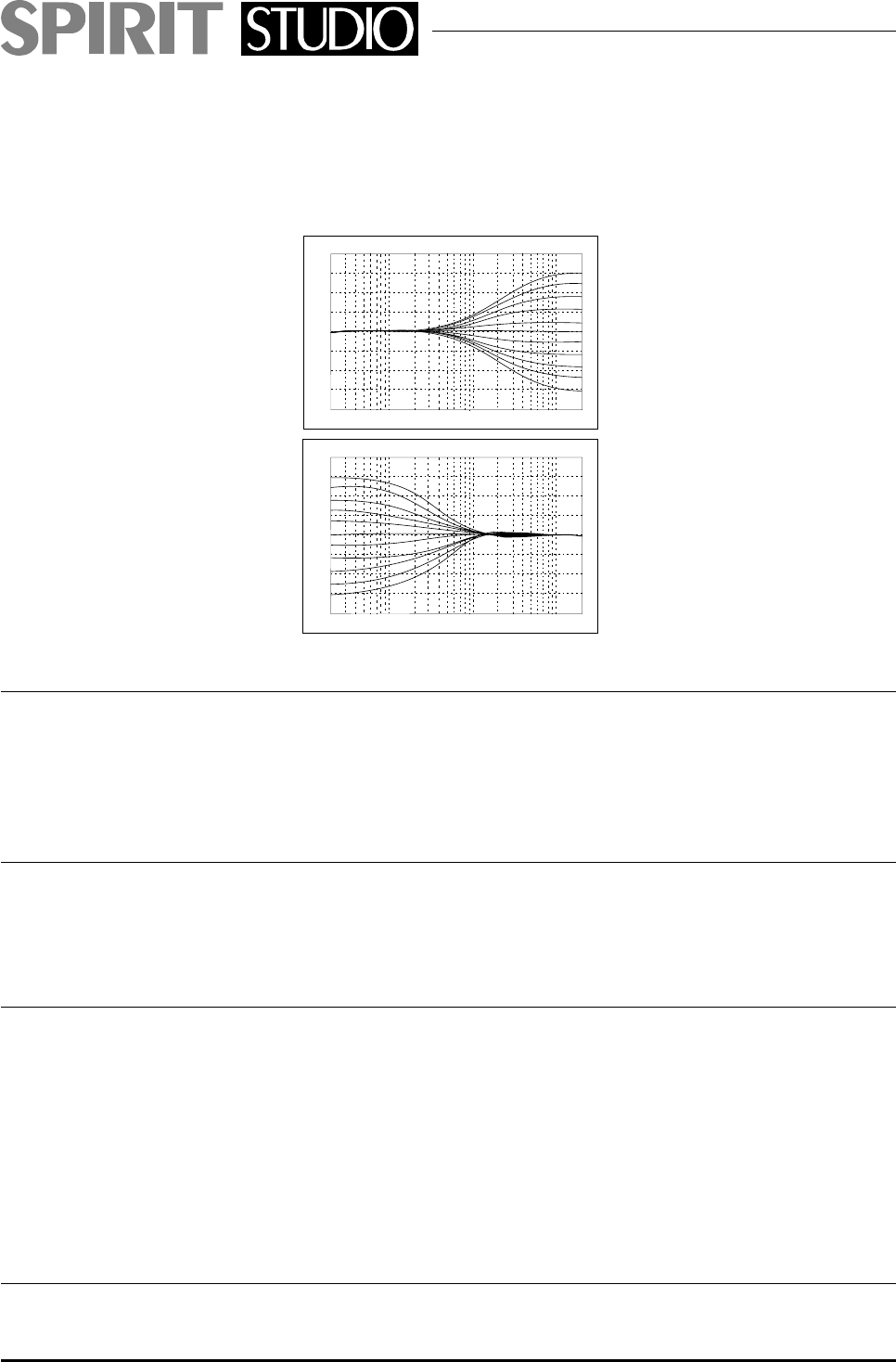
Frequency Response Curves of the Equaliser
20.0
15.0
10.0
5.0
0.0
-5.0
-10.0
-15.0
-20.0
20
1k 10k 20k
100
dB
Frequency/Hz
LF Section
20.0
15.0
10.0
5.0
0.0
-5.0
-10.0
-15.0
-20.0
20
1k 10k 20k
100
dB
Frequency/Hz
HF Section
the trimmers.
32. AUXILIARY MASTER
Each of the Auxiliary Send busses is provided with a
rotary master level control and an AFL switch with indi-
cating LED which monitors the final output after the
fader.
33. AUXILIARY OUTPUT
The Auxiliary Send output is driven by a ground-com-
pensated amplifier to a standard
1
⁄
4
" 3 pole A gauge
jack socket.
34. STEREO EFFECTS RETURN
Four Stereo Effects Returns are provided on pairs of
1
⁄
4
"
3 poleA gauge jack sockets, to allow external equip-
ment to be returned to the mixer and routed to the
stereo Mix or Groups, without using up valuable input
channels. A mono signal may be plugged into either
socket of each pair to be fed equally to left and right
busses. The Effects Returns are electronically bal-
anced.
35. TRIM
Each pair of Effects Returns has a centre-detented TRIM
Page 18


