


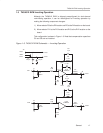

THS4012 EVM Differential Input
1-11
General
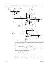
The gain of the EVM can easily be changed to support a particular application
by simply changing the ratio of resistors R6 and R5 (channel 1) and R14 and
R13 (channel 2) as described in the following equation:
Noninverting Gain
1
R
F
R
G
1
R
6
R
5
and 1
R
14
R
13
In addition, some applications, such as those for video, may require the use
of 75-Ω cable and 75-Ω EVM input termination and output isolation resistors.
Any of the resistors on the EVM board can be replaced with a resistor of a
different value; however, care must be taken because the surface-mount
solder pads on the board are somewhat fragile and will not survive many
desoldering/soldering operations.
External factors can significantly affect the effective gain of the EVM. For
example, connecting test equipment with 50-Ω input impedance to the EVM
output will divide the output signal level by a factor of 2 (assuming the output
isolation resistor on the EVM board remains 50 Ω). Similar effects can occur
at the input, depending upon how the input signal sources are configured. The
gain equations given above assume no signal loss in either the input or the
output.
Frequency compensation capacitors C3 and C6 may need to be installed to
improve stability at lower gains. The appropriate value depends on the
particular application.
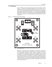
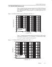
The EVM circuit board is an excellent example of proper board layout for
high-speed amplifier designs and can be used as a guide for user application
board layouts.
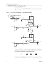
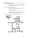
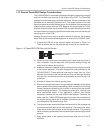
1.7.2 Differential Input, Inverting Operation
Configure the THS4012 EVM for differential inverting operation by removing
two resistors and adding a resistor on the board:
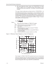
1) Move resistor R3 to the R2 location and R5 to the R4 location on the board.
2) Move resistor R11 to the R10 location and R13 to the R12 location on the
board.
3) Remove resistors R1 and R9.
4) Add a 100-Ω resistor to the R8 location on the board.
This configuration (inverting) is shown in Figure 1–5. For a inverting differential
input, R8 should be 200 Ω to match a 50-Ω source impedance. Note that
compensation capacitors C3 and C6 are not installed.