


General PowerPAD Design Considerations
1-18
General
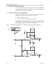
8) With these preparatory steps in place, the THS4012DGN IC is simply
placed in position and run through the solder reflow operation as any
standard surface-mount component. This results in a part that is properly
installed.
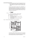
The actual thermal performance achieved with the THS4012DGN in its
PowerPAD package depends on the application. In the example above, if the
size of the internal ground plane is approximately 3 inches × 3 inches, then the
expected thermal coefficient, θ
JA
, is about 58.4 C/W. For comparison, the
non-PowerPAD version of the THS4012 IC (D-package in SOIC) is shown. For
a given θ
JA
, the maximum power dissipation is shown in Figure 1–9 and is
calculated by the following formula:
P
D
T
MAX
–T
A
JA
Where:
P
D
= Maximum power dissipation of THS4012 IC (watts)
T
MAX
= Absolute maximum junction temperature (150°C)
T
A
= Free-ambient air temperature (°C)
θ
JA
= θ
JC
+ θ
CA
θ
JC
= Thermal coefficient from junction to case (4.7°C/W) for
THS4012DGN (PowerPAD)
θ
JC
= Thermal coefficient from junction to case (38.3°C/W) for
THS4012D (SOIC)
θ
CA
= Thermal coefficient from case to ambient air (°C/W)
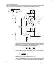
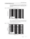
Figure 1–9. Maximum Power Dissipation vs Free-Air Temperature
2
0
0–40
2.5
3
100
3.5
–20 80
.5
1
1.5
Maximum Power Dissipation – W
6020 40
T
A
– Free-Air Temperature – °C
T
J
= 150°C
DGN Package
θ
JA
= 58.4°C/W
2 oz Trace and
Copper Pad
with Solder
DGN Package
θ
JA
= 158°C/W
2 oz Trace and
Copper Pad
without Solder
THS4012
SOIC – Package
θ
JA
= 166.7°C/W
No Air Flow
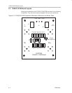
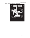
Even though the THS4012 EVM PCB is smaller than the one in the example
above, the results should give an idea of how much power can be dissipated
by the PowerPAD IC package. The THS4012 EVM is a good example of proper
thermal management when using PowerPAD-mounted devices.