


Using the THS4012 EVM With Differential Inputs
1-14
General
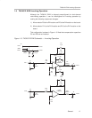
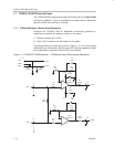
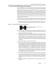
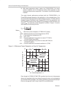
1.8 Using the THS4012 EVM With Differential Inputs
The THS4012 EVM operates from power-supply voltages ranging from ±5 V
to ±15 V. Move resistors on the board as detailed above for either noninverting
or inverting operation to configure the EVM for differential input operation.
Signal inputs on the module are terminated for 50-Ω nominal source
impedance. An oscilloscope is typically used to view and analyze the EVM
output signal.
1) Ensure that all power supplies are set to
OFF
before making power supply
connections to the THS4012 EVM.
2) Connect the power supply ground to the module terminal block (J2)
location marked
GND
.
3) Select the operating voltage for the EVM and connect appropriate split
power supplies to the module terminal block (J2) locations marked
–VCC
and
+VCC
.
4) Connect an oscilloscope
across
the module SMA output connectors
(J3
and
J5)
through a 50-Ω nominal impedance cable (an oscilloscope having
a 50-Ω input termination is preferred for examining very high frequency
signals).
5) Set the power supply to
ON
.
6) Connect the differential signal input
across
the module SMA input con-
nectors
(J1
and
J4)
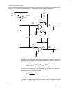
The differential EVM input is terminated with an equivalent 50-Ω impedance
for each input. With a 50-Ω source impedance, the voltage seen by the
THS4012 amplifier IC on the module will be the source signal voltage
applied to the EVM. This is due to the voltage division between the source
impedance and the EVM equivalent input resistance.
7) Verify the differential output signal on the oscilloscope.
The signal shown on an oscilloscope with a 50-Ω input impedance will be
the actual THS4012 amplifier IC output voltage. This is due to the voltage
division between the output resistors (R7, R15) and the oscilloscope input
impedance.
1.9 THS4012 EVM Specifications
Supply voltage range, ±V
CC
±5 V to ±15 V. . . . . . . . . . . . . . . . . . . . . . . . . . . .
Supply current, I
CC
17 mA typ. . . . . . . . . . . . . . . . . . . . . . . . . . . . . . . . . . . . . . .
Input voltage, V
I
±VCC, max. . . . . . . . . . . . . . . . . . . . . . . . . . . . . . . . . . . . . . . . .
Output drive, I
O
90 mA. . . . . . . . . . . . . . . . . . . . . . . . . . . . . . . . . . . . . . . . . . . . .
For complete THS4012 amplifier IC specifications and parameter
measurement information, and additional application information, see the
THS4012 data sheet, TI Literature Number SLOS216.