


THS4012 EVM Board Layouts
2-4
Reference
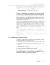
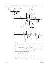
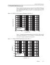
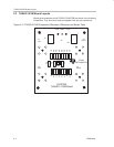
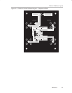
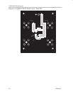
2.3 THS4012 EVM Board Layouts
Board layout examples of the THS4012 EVM PCB are shown in the following
illustrations. They are not to scale and appear here only as a reference.
Figure 2–2. THS4012 EVM Component Placement Silkscreen and Solder Pads
+
+VCC
C1
C2
–VCC
U1
J2
GND
R1
J3
Vout1
SLOP230
THS4012 EVM Board
INSTRUMENTS
+
TEXAS
R2
R3
R4
R5
R6
C3
R7
C5
C4
R8
R9
R10
R11
R12
R13
R14
C6
R15
J5
Vout2
J1
Vin1
J4
Vin2