


THS4012 EVM Differential Input
1-12
General
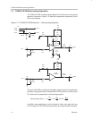
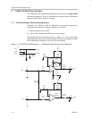
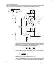
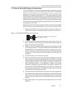
Figure 1–5. THS4012 EVM Schematic — Differential Input (Inverting Operation)
C1
6.8 µF
–VCC
1
GND
2
+VCC
3
J2
C2
6.8 µF
–VCC
+VCC
–
+
U1:A
THS4012
1
4
8
2
3
R4
1 kΩ
R6
1 kΩ
+VCC
C3
x µF
R7
49.9 Ω
Vout1
J3
C4
0.1 µF
–VCC
R2
0 Ω
J1
Vin1
R8
100 Ω
–
+
U1:B
THS4012
7
6
5
R12
1 kΩ
R14
1 kΩ
C6
x µF
R15
49.9 Ω
Vout2
J5
R10
0 Ω
J4
Vin2
C5
0.1 µF
The gain of the EVM inputs can easily be changed to support a particular
application by changing the ratio of resistors R6 and R4 (channel 1) and R14
and R12 (channel 2) as described in the following equation:
Inverting Gain
–R
F
R
G
–R
6
R
4
and
–R
14
R
12
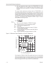
R4 and R12 form part of the input impedance and R8 should be adjusted in
accordance with the following equation:
R
8
2
R
4
R
T
R
4
–R
T
where R
T
is the termination resistance and R4 = R12.
In addition, some applications, such as those for video, may require the use
of 75-Ω cable and 75-Ω EVM input termination and output isolation resistors.