


Keyboard Stand Assembly
CLP-380 Owner’s Manual
118
Appendix
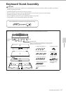
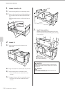
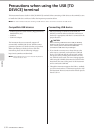
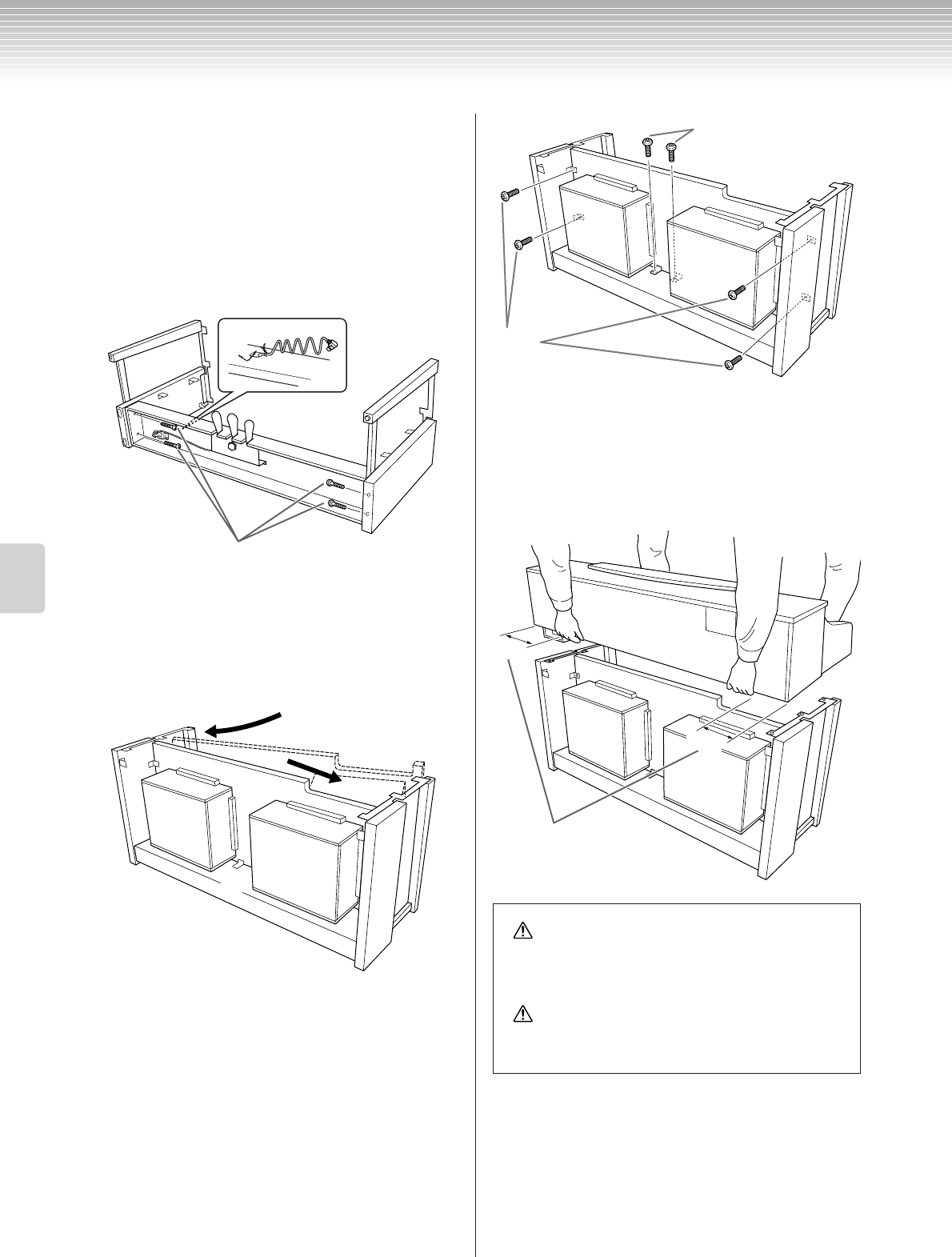
1. Attach E and F to D.
1-1 Secure D using the four 6 x 25mm long screws.
1-2 Remove the twist tie from the folded pedal cord.
Do not remove the twist tie located next to the
hole.
Don’t discard the twist tie, you’ll need it later in
step 6.
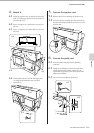
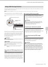
2. Attach B.
2-1 Insert B between E and F as shown in the
illustration.
2-2 Align and attach B to the front side of D, E and F.
2-3 Secure B using the 4 x 14mm thin screws.
*Insert two screws into the smaller holes on the
brackets.
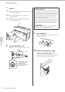
2-4 Te mporarily secure with 4 x 14mm thin screws.
*Insert four screws into the smaller holes on the
brackets.
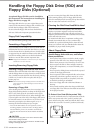
3. Lay A into position.
Align the screw threads on the bottom of A with
the screw threads of E and F, while gently lowering
A into position.
E
D
F
1-2
1-1
F
E
B
D
CAUTION
Fingers can become pinched between the main unit and
the rear or side panels, be extra careful so as not to drop
the main unit.
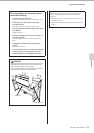
CAUTION
Do not hold the keyboard in any position other than the
position shown in the illustration.
2-3
2-4
A
F
E
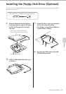
15cm
15cm
Place your hands
at least 15 cm from either
end of A when positioning it.