


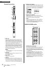

Touch screen
Owner’s Manual
20
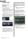
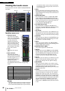
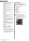
Viewing the touch screen
The touch screen of the QL series is broadly divided into
two areas.
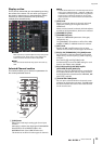
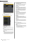
Function access area
1 Selected channel
This shows the number,
name, icon, and channel
color of the channel that is
currently selected for
operation. Pressing the
minus indication here will
switch to the preceding
channel, and pressing the
plus indication will switch
to the next channel.
2 Time
This shows the current
time.
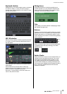
3 Status Indicator
This shows the current
status. Normally it indicates
the name of the user who is
currently logged in (i.e., is
authenticated and able to
operate the system).
The following table shows
the displayed content and the corresponding
status.
* The type of signal being cue-monitored (IN/OUT/DCA/KEY
IN/EFFECT) is shown in the upper part of the cue meter.
NOTICE
An ACCESS indicator appears in the function access area
while data is being accessed (saved, loaded, or deleted).
Do not disconnect the USB flash drive or power-off the QL
unit while this indicator is shown. Doing so may damage
your flash drive, or may damage the data in the QL unit or
on your media device.
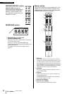
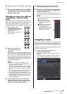
4 HELP
Pressing this button will show on-line help in the
main area. To view the on-line Help, first you must
load the Help file into the QL series console from a
USB flash drive.
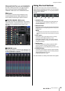
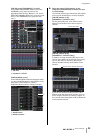
5 SENDS ON FADER
Press this button to switch to SENDS ON FADER
mode, where you can use the faders of the top
panel to adjust the MIX/MATRIX send level. During
this time, the function access area will switch to a
screen that enables you to select the
send-destination MIX/MATRIX bus.
6 CH JOB (Channel Job)
Press this button to display the CH JOB menu,
which you can make settings for channel grouping
and linking, and then select the function to
operate.
7 I/O DEVICE
When you press this button, the I/O DEVICE screen
will appear in the main area, allowing you to make
I/O device settings and external head amp settings.
8 MONITOR
When you press this button, the MONITOR screen
will appear in the main area, allowing you to edit
the monitor or oscillator settings.
9 RACK
When you press this button, the VIRTUAL RACK
screen will appear in the main area, allowing you to
edit the GEQ or effect settings.
0 MONITOR LEVEL KNOB
This control adjusts the monitor level.
A METER
Displays the level of the STEREO bus (L/R), MONO
bus (M), and cue signal (CUE). When you press this
field, the METER screen will appear in the main area.
If you press the CUE meter area when the cue
monitor is on, the cue monitor will be canceled.
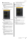
B SETUP
When you press this button, the SETUP screen will
appear in the main area, allowing you to make
basic system settings and user-specific settings.
C RECORDER
When you press this button, the recorder screen
will appear in the main area; here you can operate
and make settings for the recorder function
(USB/Nuendo Live) which allows you to record and
play back audio files.
D SCENE
This indicates the number and name of the scene
that was last stored or recalled. An
“R” symbol is
displayed for read-only scenes, and a lock icon is
displayed for write-protected scenes. If you edit the
parameters from their last stored or recalled state,
an
“E” symbol will appear in the lower right. When
you press this field, the SCENE LIST screen will
appear in the main area, allowing you to store or
recall scenes. In PREVIEW mode, this field is shown
in red.
Indication Status
OSC Oscillator enabled
TALKBACK Talkback enabled
CUE Cue monitor on*
ACCESS Accessing internal memory or USB memory
PATCHING Now performing Dante patching
ALT ALTERNATE mode enabled
PLAY Playing an audio file
REC Recording an audio file
Function access area
Main area
1
2
5
7
3
9
4
6
8
j
l
m
n
k