


148
Appendix
How to Install the
Optional Plug-in Board
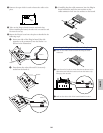
1 Turn the keyboard power off, and disconnect the power
cord. Also, if the keyboard is connected with other
external device(s), disconnect the device(s).
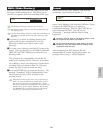
2 Move to a position facing the rear panel of the keyboard,
and remove the screws from the Plug-in board cover at
the bottom center side with a coin or a Phillips
screwdriver (three SILVER screws only). Do not remove
the other screws.
n Keep the removed screws in a safe place. They will be used when
attaching the Plug-in board cover to the keyboard again.
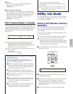
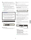
3 Remove the Plug-in board cover by pulling it to your side.
The plate incorporated with the Plug-in board cover will
appear. The plate can accommodate two Plug-in boards,
on its top and bottom: PLG1 (top) and PLG2 (bottom).
Those two can be identified by the color of the connector
cable.
PLG1: One of the cables is ORANGE and the
others are blue.
PLG2: One of the cables is YELLOW and the
others are blue.
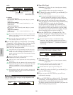
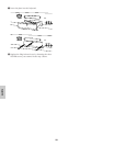
Available slot (PLG1, PLG2) differs depending on the type
of the Plug-in boards. For details, refer to the table above in
the left column.
When installing the optional Plug-in board (from when you
remove the cover to when the cover is replaced securely)
all operations must be done with the AC power cord
disconnected.
Top (PLG1)
Bottom (PLG2)
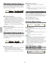
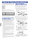
A variety of optional Plug-in boards sold separately let you
expand the voice library of your instrument. The following
types of Plug-in boards can be used with your instrument.
● PLG150-AN
● PLG150-PF
● PLG100-XG
● PLG150-VL
● PLG150-DX
● PLG100-VH
n See page 32 for detailed explanations for each board.
Available slot (PLG1, PLG2) differs depending on the type of
the Plug-in boards. Please take it into consideration before
installation.
n Although the PLG100-VL and PLG100-DX can also be installed,
some of the functions are not available.
Precautions When Installing
the Optional Boards
Remember the following precautions and install the Plug-in
boards properly by following the steps as written.
• Handle the Plug-in boards with care. Dropping or
subjecting the Plug-in board to any kind of shock may
cause damage or result in a malfunction.
• Be careful of static electricity. There are times when static
electricity affects the IC chips on the Plug-in board.
Before you lift the optional Plug-in board, to reduce the
possibility of static electricity, touch the metal parts other
than the painted area or a ground wire on the devices that
are grounded.
• Do not touch the exposed metal parts in the circuit board.
Touching these parts may result in a faulty contact.
• When moving a cable, be careful not to let it catch on the
circuit Plug-in board. Forcing the cable in anyway may
cut the cable, cause damage, or result in a malfunction.
• Before starting installation, be sure that you have a coin
or a Phillips screwdriver at hand.
• Be careful not to misplace any of the screws since all of
them are used.
• Do not use any screws other than what are installed on
the instrument.
• When inserting Plug-in boards and connecting cables,
make sure that you check that they are inserted and
connected properly. Improperly inserted Plug-in boards
and cables may cause faulty contacts and an electrical
short circuit which may cause damage or result in a
malfunction.
• After mounting the Plug-in board be sure to tighten the
screws as directed so it is completely stable and does not
move in any way.
PLG1/PLG2
PLG1 only
PLG2 only
Single-part Plug-in Boards (PLG150-AN, PLG150-PF,
PLG150-VL, PLG150-DX)
Effect Plug-in Board (PLG100-VH)
Multi-part Plug-in Board (PLG100-XG)
About the Plug-in Boards (Optional)