


Operating Manual - ne24.24M Matrix Processor
16
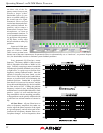
Bessel
These filters, as implemented on the ne24.24M, are always -3dB at the displayed crossover frequency. Bessel
filters are used because they have a maximally flat group delay. Stated another way, Bessel filters have the most linear
phase response. When a Bessel HPF and LPF of the same crossover frequency are summed, the combined response is
+3dB for 12dB/oct, 18dB/oct, and 48dB/oct Bessel filters, and -2dB for 24dB/oct Bessel filters. One of the outputs must
be inverted when using either 12dB/oct or 18dB/oct Bessel crossover filters or else the combined response will have a
large notch.
Linkwitz-Riley
The 12 dB/oct, 24dB/oct, an 48dB/oct Linkwitz-Riley filters individually are always -6dB at the displayed cross-
over frequency, however the 18dB/oct Linkwitz filters individually are always -3dB at the displayed crossover fre-
quency. The reason for this is that Linkwitz-Riley filters are defined in terms of performance criterion on the summing
of two adjacent crossover HPF and LPF filters, rather than defined in terms of the pole-zero characteristics of individual
filters. The 18dB/oct Linkwitz-Riley individually are 18dB/oct Butterworth filters in that they have Butterworth pole-
zero characteristics and also satisfy the criterion for Linkwitz-Riley filters.
When a Linkwitz-Riley HPF and LPF of the same crossover frequency are summed, the combined response is
always flat. With 12dB/oct Linkwitz-Riley crossover filters, one of the outputs must be inverted or else the combined
response will have a large notch at the crossover frequency.
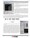
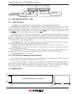
8.2c Output Delay
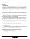
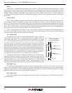
Output delay can be used to time align discrete drivers within a cabinet or
cluster using short delay times, or align multiple drivers in different locations
using longer delay times. For a thorough long-delay explanation, see section
9.1e. The following example illustrates a use of short delay to time align speak-
ers within a group: A typical three way speaker cluster has low end, midrange,
and high frequency drivers all located near one another. The different drivers for
each frequency band are not necessarily the same physical depth with respect to
the front of the loudspeaker cluster, so there exists the problem of the same sig-
nals (at the crossover points) arriving at the cluster "wavefront" at different times,
creating undesirable wave interaction such as frequency peaks or cancellation.
The solution in this case, rather than fixing the frequency anomalies with EQ, is
to slightly delay the signal to the drivers closest to the cluster front.
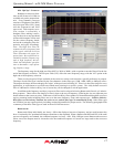
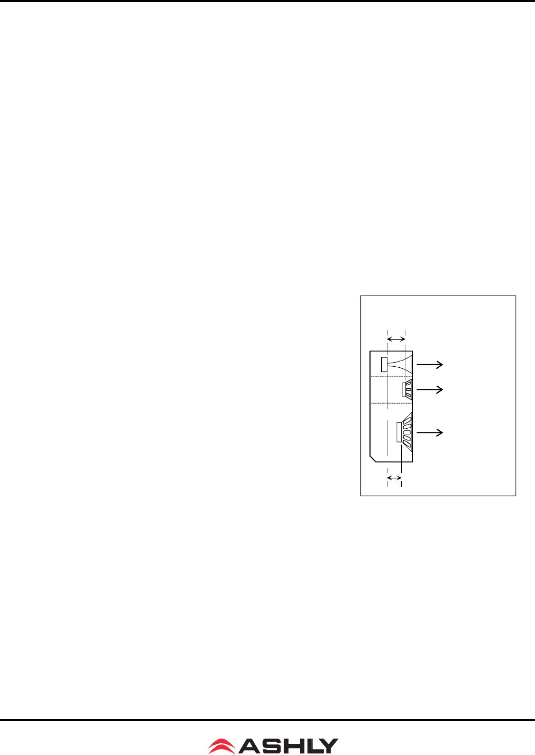
Using the location of the driver diaphragm farthest back as a reference point,
measure the distance to other drivers in the cluster, and set the output delay for
each accordingly, with the driver diaphragm closest to the front getting the long-
est delay and the driver at the very back getting no delay at all. The minimum
adjustment is 0.02 milliseconds, or about 1/4 inch. When appropriate, always
time align the loudspeakers before applying EQ to the outputs of the ne24.24M.
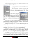
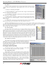
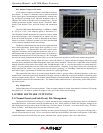
8.2d Output EQ
The Protea ne24.24M Output EQ section is the same as the input EQ (see section 9.1f), with the exception of the
ability to view the combined effect of input EQ for each installed and linked input channel to a given output channel.
Within the output EQ frame, each installed and linked input channel has its own <Overlay Input EQ> check box, through
which the interaction between input and output EQ is displayed.
8.2e Output Gain
Output Gain operates in the same manner as Input Gain (section 9.1d), ranging from +12dB to Off, with an option
to reverse polarity.
High - No Delay
Midrange Delay
12 Inches = 0.9mS
Low Delay
8 Inches = 0.6mS
Example: 12 Inches
Example: 8 Inches
Short Time Delay
For Driver Alignment