


Operating Manual - ne24.24M Matrix Processor
8
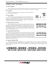
5.8 Data In/Data Out Connection
The Data In and Out connectors are used for connecting the ne24.24M to the Ashly WR-5 active wall remote
controller or RD-8C.
5.9 Factory Reset Switch
Factory reset is used to clear all user defined preset names and control values and reset them to their original
factory settings. Factory reset to the ne24.24M is accomplished by pressing and holding a recessed switch on the back
panel during power up. The switch is found in a small hole labelled “Reset”. There is a 10 second countdown in the
front panel LED display to indicate a factory reset is about to occur. Releasing the switch or shutting off power at any
time during the countdown will stop the factory reset from occurring. At the end of the countdown, the letters "Fr" flash
in the display for about 20 seconds until factory reset is complete. In addition to resetting all presets to factory default,
any password or security settings will be lost when a factory reset is performed.
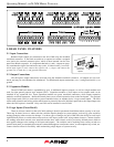
5.10 AC Inlet and Power Switch
A detachable AC power cord is used on the ne24.24M. Since the internal universal power supply works from 90
to 240 VAC 50-60Hz, the only change necessary for use with a different AC mains connection is the appropriate AC
power cord. The AC power switch is found on the back of the unit.
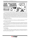
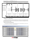
6. EXPANSION MODULE INSTALLATION
The Ashly ne24.24M can be ordered from the factory with expansion modules pre-installed to suit the application,
or as a 4 x 4 base unit. Should the need arise to add input or output capacity at a later time, as well as logic output
function, additional modules can be purchased and easily installed in the field.
There are a total of four expansion slots available, and each slot accepts either an input, an output, or a logic
output module (GPO). The ne24.24M as well as Protea NE Software autodetect if a slot has been filled, and whether it
is an input, output, or logic output. The software interface automatically updates to reflect the current ne24.24M expan-
sion slot configuration. The logic output expansion module can be installed into any slot, however only one logic output
module can be installed.
Please note that while field installation is not complicated, there is a risk of ESD (electrostatic discharge) damage
to circuit board components if the board is improperly handled.
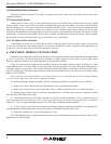
To install an additional expansion module, refer the following procedure to a qualified service technician:
1.) Remove AC power cord from back of unit and place unit on grounded work surface.
2.) Remove the seven top cover screws and remove cover. Remove expansion slot covers from back panel.
3.) Discharge any personal static by touching a grounded object. Carefully remove the new expansion card and
flat cable from the ESD protective bag.
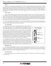
4.) Follow the instructions in the above drawing for installing expansion modules. Ashly recommends placing
input expansion modules starting with EXP1, and placing output expansion modules starting from EXP 4 and working
backwards. This way input and output channels are continuously numbered up from channel 1.
6.) In some cases it may be necessary to remove an existing expansion card before installing a new adjacent one.
Certain motherboard flatcable headers may be inaccessible with modules installed above them.
7.) Make sure all hardware is secure, then replace top cover.
For further information on expansion module assembly or proper ESD protection, please contact the Ashly service
department at 1-800-828-6308.