


17
Operating Manual - ne24.24M Matrix Processor
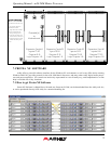
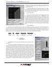
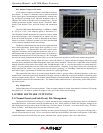
8.2f Output Compressor/Limiter
A full function compressor/limiter is included on each out-
put channel. A limiter is commonly used to prevent transient
audio signal spikes from damaging loudspeakers, manage ana-
log and digital recording levels, optimize broadcast levels, or
"thicken" the sound of an audio source (compression). The ad-
justable parameters include Limiter In/Out, Threshold, Ratio,
Attack Time, Release Time, and Link Group, and Attenuation
Bus.
The ne24.24M limiter threshold range is -20dBu to +20dBu,
or -24VU to +16VU if the metering option is selected to VU.
The Threshold control determines the signal level above which
gain reduction begins, and is indicated by an amber LED (S/L)
on the ne24.24M face panel, as well as indicated in the Matrix
Meters in software. Increases in audio level above the threshold
will be reduced according to the ratio settings.
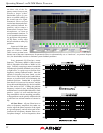
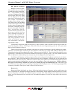
The Ratio control determines the amount of gain reduction
above limiter threshold. Ratio ranges from a gentle 1.2:1 to a
very abrupt INF:1. To illustrate how the ratio control works,
imagine a commonly used loudspeaker protection ratio of 10:1,
which means that for every input signal increase of 10 dB above
threshold, the output level will only increase by 1dB. The higher
the ratio, the more pronounced the audio effect, so use the lowest ratio possible to sufficiently address the problem.
Attack and Release settings adjust the time it takes the limiter to engage and then disengage when the signal
increases above threshold and then subsequently falls back below threshold. Attack time is adjustable from 0.2ms/dB
through 50ms/dB, while release time ranges from 5ms/dB through 1s/dB. A very fast attack time can sound unnatural,
while a very long attack time can miss some of the initial transient. Similarly, a very short release time can make the
audio sound uneven, while a very long release time can create "pumping", or "breathing" characteristics depending on
the kind of signal. Experiment to find the best solution for a given application.
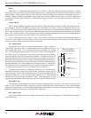
The Attenuation Bus allows up to four output channels within a group to share a threshold detector, so that any
channel with a transient signal above threshold will apply equal gain reduction to all other channels within that group
which is assigned to the link bus. The channel which furthest exceeds threshold will determine the resulting reduction
on all channels selected to the attenuation bus. The channel limiter attenuation bus is particularly useful when process-
ing stereo signals.
8.2g Output Mute
Output Mute turns off an output channel. When an output channel is muted, that channel’s red mute LED on the
face panel is lit. To mute or unmute all outputs at once, go to the <Mute> menu heading.
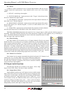
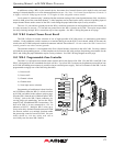
9. OTHER SOFTWARE FUNCTIONS
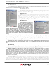
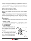
9.1 Channel Preset (and Sub Preset) File Management
The Protea ne24.24M will store up to 31 named internal presets, each preset storing control data for all channels
and audio functions. Preset names must be 20 characters or less. While working in Protea NE Software, changes to an
individual preset can be saved to the ne24.24M using <File/Save Preset To Protea>, or saved to the PC using <File/Save
Preset To Disk>. Individual preset files use the extension (*.pne).
Sub Presets: Instead of saving or recalling an entire preset affecting all functions, a sub-preset affecting only a
sub-set of functions may be used. To save a sub-preset, check the boxed labelled <Selected for sub-presets> in the audio
control functions to be stored in the sub preset, and then click <preset options>, then <Save Sub Preset>.