19
Operating Manual - ne24.24M Matrix Processor
In addition to using a WR-1 as the control device, the remote level control feature can be used for relay activated
muting of selected channels, as in a fire alarm application (see sec. 16). Note: Use Protea System Software version 6.1.4
or higher, and ne24.24M program version 1.5 or higher to allow assignable remote control.
Level control is "attenuate only" meaning that the maximum setting of the control potentiometer (fully clockwise)
results in 0 dB gain of the controlled channel. A label template can be found on the Ashly website for printing input or
output channel names under control of the WR-1 and sliding the paper behind the mylar overlay windows.
The two +5V pins and two ground pins on the WR-1 euroblock connector are tied together on the circuit board, so
it is only necessary to run one +5V line and one ground line to the WR-1 from the ne24.24M. These pins are provided
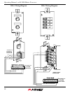
for daisy-chaining multiple WR-1 controllers (up to four) together. See WR-1 Wiring Diagram on next page.
10.2 WR-2 Contact Closure Preset Recall
The WR-2 allows for remote selection of one of eight possible ne24.24M presets via interlocking push-button
switches. Each pushbutton switch connects to a terminal block pin on the WR-2 circuit board, which in turn must be
wired to the ne24.24M back panel euroblock connector labeled "Preset Recall". Do not connect the WR-2 remote level
control ground to any other external grounds.
The terminal numbers 1-8 correspond to the first 8 Preset Memory locations in the ne24.24M. Pressing a button
will load the corresponding preset. A label template can be found on the Ashly website for printing preset names for the
WR-2 and sliding the paper behind the mylar overlay windows. See WR-2 Wiring Diagram on next page.
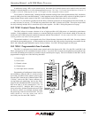
10.3 WR-5 Programmable Zone Controller
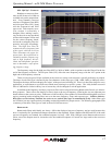
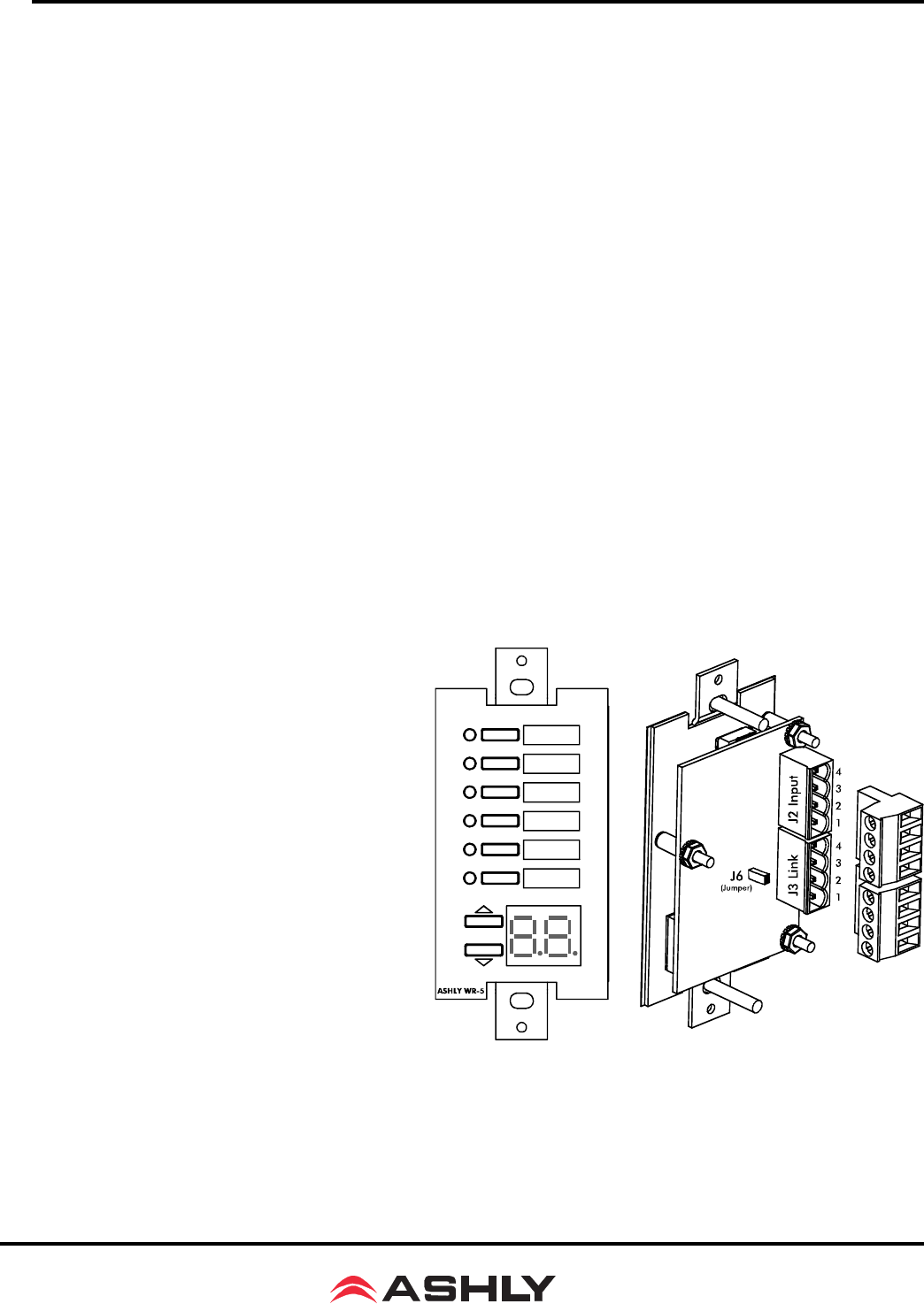
The WR-5 is a microprocessor based remote control unit for the Protea ne24.24M. Like the WR-1 and WR-2, the
WR-5 is designed to fit into a standard electrical wall box. Up to four WR-5 remotes can be phantom powered from one
ne24.24M, and adding more remotes is possible using an external power supply. Each of six buttons on the WR-5 can be
programmed to engage one of the following functions:
1) Preset recall
2) Preset scroll
3) Channel volume
4) Channel mute
5) Zone input source selection
Programming of each button is done from Pro-
tea NE Software when the WR-5 is wired to its host
ne24.24M, and added to the software project page.
Wire the WR-5 from the ne24.24M back panel “WR-
5 Wiring” jack to the WR-5 Input connector, ob-
serving proper pin numbering, and use the WR-5
output “Link” for additional WR-5 connections. The
host ne24.24M is in turn connected to a PC via
ethernet or RS-232. Multiple WR-5 units (up to
four) can be daisy-chained from the same ne24.24M
for discrete control over multiple locations under
the processing control of one ne24.24M. See your
Ashly dealer or visit the Ashly web site at
www.ashly.com for more WR-5 details.


