


Installation ~ LCD Programming
26
Technical Services Group ~ 1-800-283-5936 (USA) ~ 1-801-974-3760
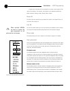
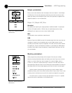
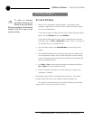
Output parameters
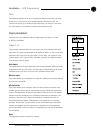
There are two main submenus under the outputs menu tree: Output 1–4 and Output
A–D/Telco Out. The two main submenus contain the same menus at the next menu
depth: gain adjust, mute and NOM (Figure 2.18). Each parameter is applied to the
respective outputs (1–4 or A–D/Telco Out).
Output 1-4, Output A-D, Telco
Gain adjust
This adjusts each output’s gain (ranging between -20dB and 20dB). In conjunction
with the LCD readout and the LED bar meter, all gated outputs can be simply
calibrated for the right level on the mix bus. Default is 0dB.
Mute
This parameter mutes a particular output channel.
NOM
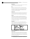
Number of open mics (NOM) corrects for increased output level when more than one
microphone is gated on. As microphones gate on, the AP400 reduces the level
according to the number of active microphones. This mode can be turned on (default
for outputs A-C, Telco) or off (default for outputs 1–4, and output D). NOM adjusts
at 10log of the number of open microphones, or approximately 3dB every time the
mic count doubles.
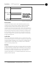
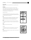
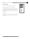
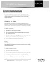
Routing parameters
When programming routing through the front-panel LCD, there are multiple
submenus (routing destinations) below the Routing menu (see Figure 2.19): route to
output 1–4, route to Telco Out, route to output A–D, route to Subbus, route to
G-Link X–Z, route to EC reference and PA, or route to G-Link Ref. Select one of
these parameters and press Enter to scroll through the inputs available for routing to
that output. When the correct input appears, press Enter to route it to that output.
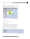
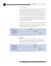
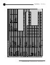
Routing consists of determining which inputs go to which outputs. When
considering routing, refer to the default routing matrix (Figure 2.20). There is also
a routing matrix worksheet at the end of this manual (see Appendix F, page 66).
The audio matrix is made of sources and destinations. There are 17 possible
input sources and 13 destinations on the AP400 matrix.
Figure 2.19. Routing parameters
LCD submenu
Figure 2.18. Output parameters
LCD submenu