


5
Introduction ~ Controls and Connections
Technical Services Group ~ 1-800-283-5936 (USA) ~ 1-801-974-3760
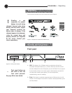
C. s/tThese buttons scroll up and down through vertical programming options
within a specific PSR1212 programming parameter or increases/decreases a
numeric value.
D. Esc. This button steps you out of a selected parameter or moves you up one
level in the menu. When a parameter has been displayed with the arrow
buttons [C], you can select it with the Enter button [B] to modify it. Then,
you can step out of the menu with the Esc button.
E. LED meter. This assignable, peak-level LED bar meter is used to display
the audio level of an input, output, or processing channel of the PSR1212.
F. Meter. Takes you directly to the Meter branch of the PSR1212’s LCD menu
tree.
G. LED 1–8. These LEDs indicate Inputs 1–8 gate status.
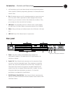
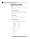
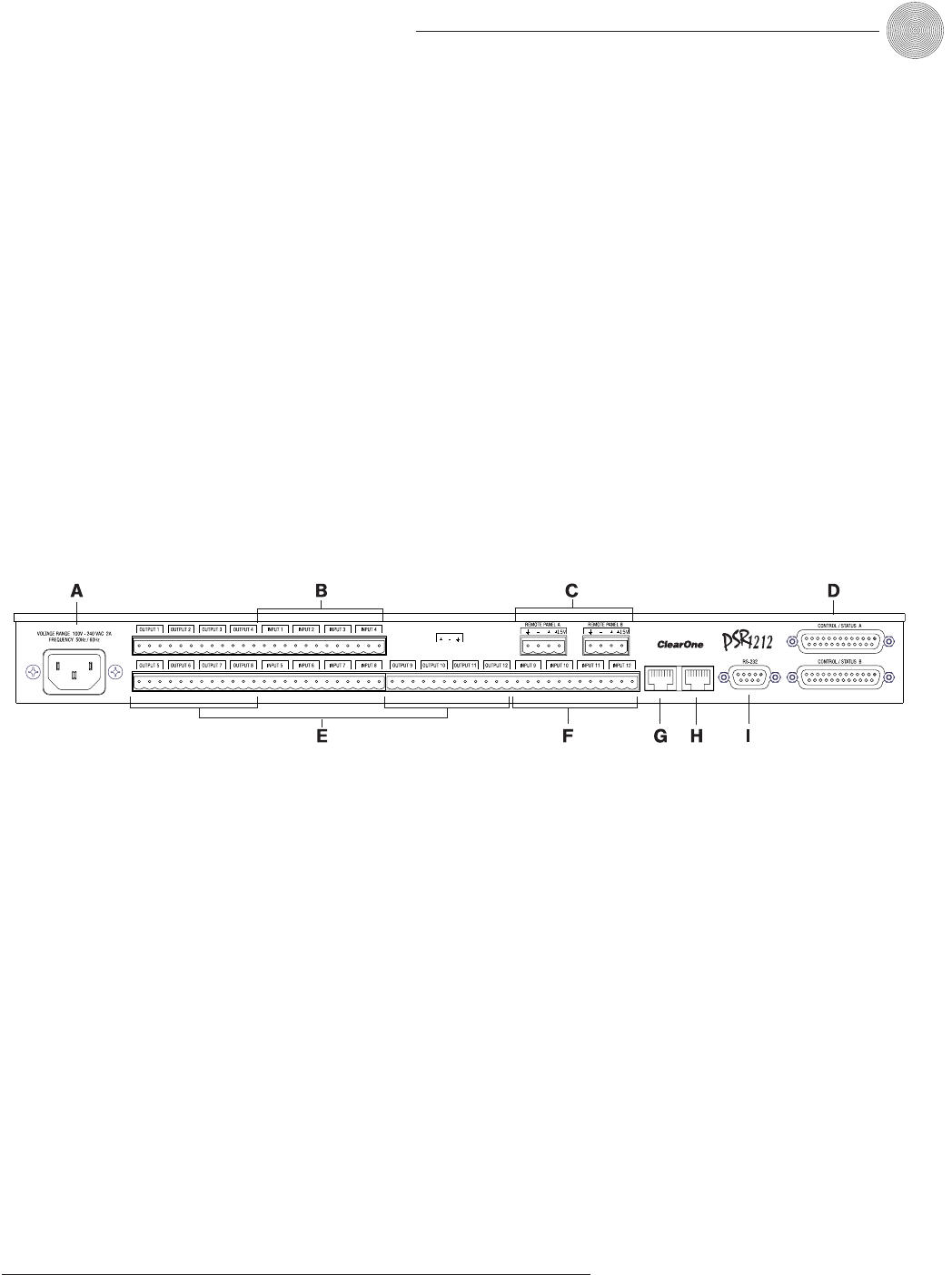
Rear panel
A. Power. This power module accommodates power ranging from
100–240VAC, 50/60Hz. The module uses an IEC-type connector. No
switching is required.
B. Inputs 1–8. These Phoenix block connectors are for connection of eight
mic-level or line-level (selectable) inputs. These connectors are typically
used for mics, but can be configured for use with VCRs, CD players, etc.
These inputs can be mixed in any gated or non-gated combination and
routed to any of the 12 outputs. Default input level is -55dBu. For more
information about input adjustments, see page 32. For electrical
specifications, see Appendix A: Specifications.
C. RS-485 Remote Panel A/B Port. These four-pin Phoenix connector ports
allow you to control the PSR1212 with the ClearOne Control Panel or XAP
IR Remote Control.
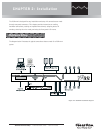
Expansion Bus
In
Out
Figure 1.3. Rear panel connections