


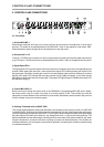

3. QUICK START
This paragraph describes in an overview the most important steps for a trouble-free operation of the DRM
4000 in your PA-system. For a more detailed description of specific functions when using the DRM 4000
in combination with the DPM 4000, please refer to chapter 6.4. For further details on the functioning and
the configuration of the DRM 4000, please refer to the corresponding paragraph in the handbook.
POWER SUPPLY
Connect the DRM 4000 to a 24 V DC power source via the 6.3mm flat-connectors (14) on the rear panel.
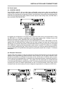
AUDIO CONNECTIONS
Before integrating and initially operating the DRM 4000 in your PA-system, you should determine which
system configuration you are using. Please refer to chapter 8 “CONFIGURING THE DRM 4000" for a
wiring example for the BASIC CONFIGURATION 8-in-2 mixer as well as for notes on how to configure
the DRM 4000. Please refer to the additional sheet ”DRM 4000 FACTORY CONFIGURATION" for an
overview of the factory pre-set assignment of the BASIC CONFIGURATION and the CONTROL INPUTS.
After doing so, connect the DRM 4000 according to the chosen configuration. Do not power-on any
connected audio signal source yet.
POWER ON OPERATION
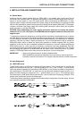
After including the DRM 4000 in your PA-system and before operating it for the first time, please set the
input controls MIC/LINE 1-4 (4) and AUX 1-4 (7) all the way counterclockwise, so that actually no audio
signal is fed to the audio outputs. Proceed in the same way with the gain controls (24) of the input channels
MIC/LINE 1-4 on the rear panel of the appliance. Set them to +10 dB (counterclockwise margin). The
DRM 4000 is factory pre-configured to be used as 8-in-2 mixer, which is a universal configuration in stereo
mode. In case the appliance had previously been operated, it may start-up in any other configuration.
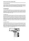
LEVEL SETTING
Set both master controls (10) to their counterclockwise margins, so that actually no audio signal is present
at the audio outputs of the DRM 4000. Now, activate the previously connected sound source. If this audio
signal source is connected to one of the MIC/LINE-inputs, carefully turn the corresponding gain control
(24) on the rear panel of the appliance in clockwise direction. The green SIGNAL-LED (3) indicates signal
presence. If the red PEAK-LED (3) lights, reducing the input amplification by turning the gain control
counterclockwise will prevent possible distortion. Now, you can turn the input control MIC/LINE (4) or AUX
(7) as well as both MASTER-controls (10) clockwise. The audio signal is present at the XLR-type output
connectors (19) on the rear panel of the DRM 4000 and the momentary level reading is indicated via the
level-meter LED-chains (11).
QUICK START
3-1