


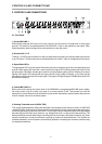
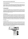
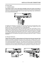
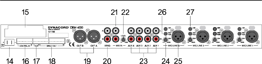
2.2 Rear Panel
14, 24 V power supply
These two 6.3mm flat-connectors are utilized to supply the DRM 4000 with an operating voltage of 24 V
DC. Whenever incorporating the DRM 4000 in an intercom system, using the system’s already existing
supply voltage of 24 V is recommended. For stand-alone operation use the optionally available mains
adapter (NRS 90257). Make sure to mind the correct polarity (+ = +24V, - = Ground) when connecting
the power supply.
15, REMOTE INTERFACE port
This port allows retrofitting an optional serial interface (RS-232 or RS-485). For further detail, please refer
to chapter 9.3 “How To Install Extensions”.
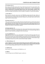
16, CONTROL IN
These control inputs provide access to eight programmable internal states, including: signal routing,
ducking control (priority function), level settings, mute, etc. Connecting it to ground activates a control
input. The configuration is factory pre-set for using the DRM 4000 in a multitude of applications. Utilizing
a serial interface (optionally available) allows configuring the functions of the eight control inputs via
PC-software according to your personal needs. These setting can be saved in the DRM 4000. For details
on the pin-assignment and an example of how connection is established, please refer to chapter 4.4.1.
17, External VCA-control
These control contacts allow the connection of two external potentiometers for remotely controlling the
volume settings of Master A and B. The VCA’s of the two master outputs A or B are controlled by
DC-voltage. Please, keep in mind that audio levels of eventually prioritized microphones (Priority Override
is enabled) are not attenuated by VCA-control. For details on the pin-assignment and an example of how
connection is established, please refer to chapter 4.4.2.
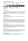
18, DIRECT OUT
Each of the eight input channels (MIC/LINE single-channel and AUX two-channel) has an individual direct
output. It is possible to internally assign the direct outputs to PRE (the signal path is split prior to the tone
control and volume setting section) or POST (the signal path is split after the tone control and volume
setting section). For details on the pin-assignment, please refer to chapter 4.3.3.
19, Master Outputs OUT A / B
These are the two balanced XLR-type outputs of the DRM 4000. They can be used as L/R-stereo or as
two separate monaural outputs, depending on the configuration of the DRM4000.
CONTROLS AND CONNECTIONS
2-3