


9.3 HOW TO INSTALL EXTENSIONS
9.3.1 How to install the Input Transformer (NRS 90233, EDP-No. 121 682)
Contents NRS 90233:
1 x Input Transformer DCN340955
Installation Instructions NRS 90233:
1. Turn off the power of the DRM 4000 and open the cover plate as described before.
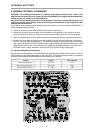
2. For installation of the transformer you first have to remove the printed board assembly 80478 (MAIN
BOARD). Start with removing the EQ-board 82228.1 by loosening its three locking-screws and tipping
the small board over to the rear. Now, loosen all screws of the printed board assembly 80478 (15
screws on the rear panel and 3 screws on the front panel, which lock the sockets in place, 7 screws
and 3 bolts on the printed board assembly itself). Also loosen the two locking screws of the front panel
on the bottom plate of the appliance. Remove the potentiometer-caps from the 8 channel controls and
the 2 master controls by pulling them off to the front. Detach the front panel. If an interface-board has
previously been installed, remove it temporarily. After slightly lifting the front of the printed board
assembly 80478, pull it to the front of the appliance so that the connectors are free of the rear panel.
Now, you are able to remove the printed board assembly 80478 so that it is accessible for installing
the transformer.
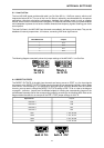
3. Remove the two resistors of the corresponding input channel (MIC/LINE 1: R1A / R2A, MIC/LINE 2:
R1B / R2B, MIC/LINE 3: R1C / R2C, MIC/LINE 4: R1D / R2D).
4. Using a suction pump, clean the holes for installing the transformer (9 holes per transformer) as well
as the holes of the previously removed resistors from soldering tin.
5. Insert the transformer into the prepared holes (position T1A for MIC/LINE 1, position T1B for
MIC/LINE 2, position T1C for MIC/LINE 3 and position T1D for MIC/LINE 4)
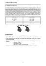
6. Solder the contacts of the corresponding transformer to the printed board assembly (9 soldering
points per transformer).
7. Reinsert all printed board assemblies and reattach the front panel following the opposite manner of
their removal. Make sure to fit all connectors and LED’s into the according holes in the front and rear
panel. Tighten all locking-screws. Reinsert the interface-board, if you have previously removed it.
8. Re-install the cover plate as described above.
INTERNAL SETTINGS
9-4