


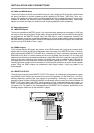

4.4 Control Inputs
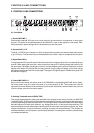
4.4.1 CONTROL INPUTS
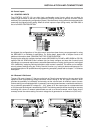
The CONTROL INPUTS (16) are eight freely configurable control inputs, which are provided via
Phoenix-type terminals on the rear of the appliance. Closing (connection to ground) a control contact
switches to the corresponding configuration (preset). Simultaneously closing several contacts selects the
preset with the highest priority setting. When all control inputs are open (idling mode), the DRM 4000 is
set to its BASIC CONFIGURATION.
As shipped, the configurations of the eight control inputs have been factory-pre-programmed for using
the DRM 4000 in a multitude of applications. For further detail, please refer to chapter 8 and to the
additional information sheet “DRM 4000 FACTORY CONFIGURATION”.
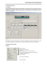
Employing the optionally available interface boards (NRS 90256 for RS-485 or NRS 90258 for RS-232)
together with the “DRM 4000 Editor” software lets you freely configure and store the 8 control inputs
according to your personal requirements; accessible parameters are: routing, ducking control, muting and
VCA. Additionally, assigning individual priorities to each contact is possible. This allows you to establish
security-relevant settings using the “Priority Override” function; e.g. routing for alert announcements. For
an exact description of all possibilities and programming examples, please refer to chapter 7.4 “Software
Description”.
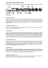
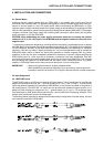
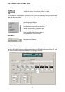
4.4.2 External VCA-Control
The two VCA-control inputs (17) that are carried out as Phoenix-type terminals on the rear panel of the
appliance allow accomplishing voltage-controlled volume setting of the two output channels, which
provides the possibility to individually and remotely set the volume levels for different rooms or areas.
Volume setting is accomplished either via externally connected potentiometers or switchable resistors or
via an externally generated DC-voltage (0V - 10V), where at 0V the output signal is not attenuated and
at 10V the output audio signal is attenuated by 90 dB. The following example shows the wiring for remotely
controlling the volume via external potentiometer as well as a second example, which shows how to
remotely control the volume setting via control voltage that is generated in an external unit (DCS 416).
INSTALLATION AND CONNECTIONS
4-3