


6. SPECIAL FEATURES OF THE DRM 4000
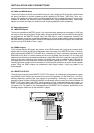
6.1 Using Ducking Control
The ducking control allows the unaltered passage of audio signals of prioritized channels (MIC/LINE 1
and / or MIC/LINE 2), while at the same time the audio signals of any other non-prioritized input channels
(e.g. background music) are attenuated to a pre-adjustable level value. The background music audio
signal fades in smoothly upon finishing the announcement.
For using the ducking function, you have to choose a configuration that includes the option PRIORITY
OVERRIDE ENABLED for one or both input channels MIC/LINE 1 and 2 (see enclosed information sheet
“DRM 4000 FACTORY CONFIGURATION”).
Owning one of the two optionally available interface boards lets you configure the DRM 4000 according
to your personal requirements.
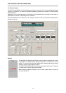
Please keep in mind that the ducking control automatically affects the corresponding output channel(s),
to which the prioritized input channel is assigned. Using the gain control for setting the input level of a
prioritized channel and while talking into the connected microphone, depending on the channel’s routing,
you should be able to see one or both yellow ducking-LED’s (9) lighting, which indicates that the ducking
function has been activated for either output channel (A or B) or for both. Otherwise, re-adjust the ducking
control’s threshold setting via the Ducking Threshold control (DUCK THR) (5). Turning the control in the
counterclockwise direction decreases the set value while turning it clockwise increases the threshold
setting.
Once the ducking threshold has correctly been adjusted (ducking-LED lights while talking into the
microphone, but stays dimmed otherwise; i.e. is not automatically activated by environmental noise), use
the two ducking controls (8) for setting the attenuation level of the non-prioritized input channels in the
setting range between 0 dB to -40 dB. The factory pre-set value is -40 dB.
6.2 LIMITER OPERATION
The two input channels MIC/LINE 1 and 2 employ an internal limiter, which provides the extremely useful
function of automatically confining the dynamic range when using the DRM 4000 in microphone
applications. Peak levels are trimmed down to a pre-set value (threshold), effectively avoiding distortion
and clipping like it might occur in close-miking applications. The limiter threshold is factory pre-set to +5
dBu, which in return provides a maximum output level of +15 dBu (10 dB amplification with the channel’s
volume control set to its clockwise margin) at the channel output. This setting is most useful for a majority
of applications. Changing the limiter threshold in a range between -10 dBu and +20 dBu is possible via
an internal trimmer.
For further detail, please refer to chapter 9.2.
Please keep in mind that the limiter is meant for equalizing drastic dynamic changes in microphone
applications. However, correctly setting the gain control of the input stage is mandatory.
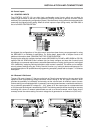
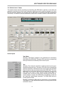
6.3 Cascading Several Units via MIX IN and SEND
Connecting the SEND output of a DRM 4000 to the MIX IN input of a second DRM 4000 doubles the
amount of available input channels. The master signal of all input channels is controlled using the master
controls at the DRM 4000 that is last in chain. The corresponding outputs are OUT A and OUT B of that
“last” DRM 4000. When employing the MIX IN input for this special purpose, set the MIX IN control to its
0 dB-mark. This ensures that the level-ratio is maintained over all units in the chain. Following this principle
it is possible to cascade up to 8 DRM 4000 units.
However, when cascading several DRM 4000 units, because of their unbalanced design, make sure not
to use long cables for connecting the SEND outputs to the MIX IN inputs. Ideally, all cascaded DRM 4000
units are installed underneath each other in a single rack.
SPECIAL FEATURES OF THE DRM 4000
6-1