


Stage 2
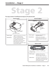
This stage consists of installing/connecting the items shown below.
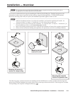
Ethernet cable
CAT 5, 5E, or 6 with T568A or T568B straight
through wiring
Where it goes: Attaches to the receiver’s
RJ-45 OUT port and to the
VoiceLift Adapter’s RJ-45 port.
What it does: Provides power to the receiver
and enables communication and
audio between the receiver and
the PoleVault switcher.
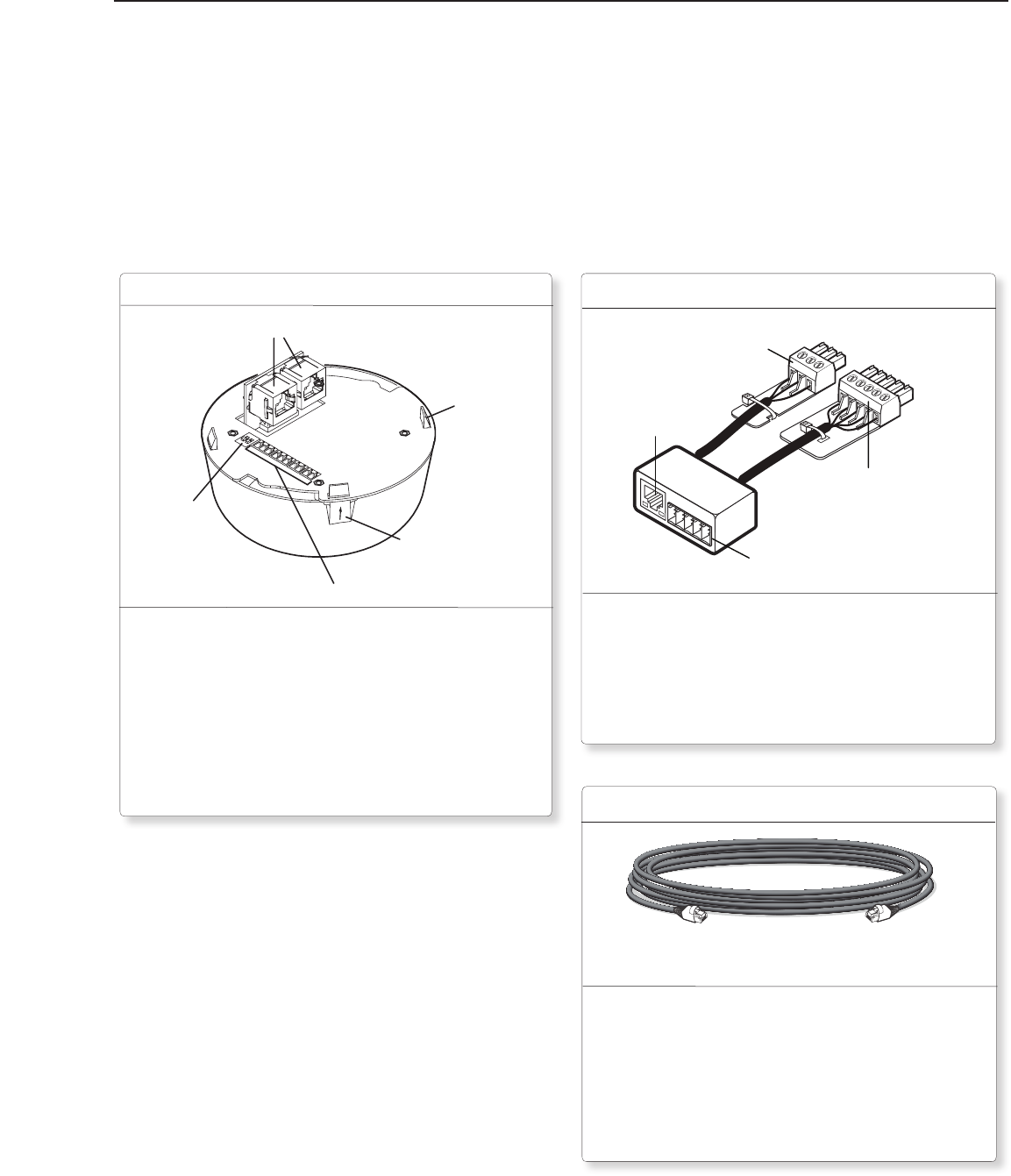
VoiceLift Adapter
Where it goes: Connects to the PVS 204 SA
PoleVault switcher.
What it does: Enables power and audio
between the VoiceLift Receiver
and the PVS 204 SA Polevault
switcher.
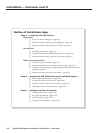
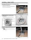
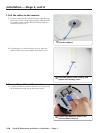
Ethernet Port
for VLR 102
Receiver
Port for MLC
Control Panel
Connector to
Aux/Mix In Port
Connector to
RS-232/MLC IR
Port
Installation — Stage 2
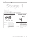
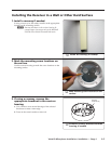
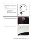
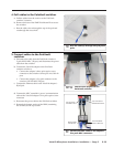
Where it goes: Attaches to the receiver’s housing
with a 1/8 clockwise turn.
What it does: Contains the photodiode IR
sensors; captive screw connectors
for auxiliary input, RS-232,
contact input, and relay output;
RJ-45 connectors for power,
communication, and audio output;
and two DIP switches.
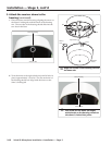
Receiver dome
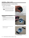
Locking
Tab (4)
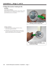
RJ-45 Connectors
Captive Screw Connectors
DIP Switches
Locking Tab
with Arrow
2-9
VoiceLift Microphone Installation • Installation — Stage 2