


VoiceLift Microphone Installation • Introduction — Planning
Introduction — Planning
1-2
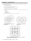
Before You Begin — Planning the Installation
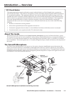
Before starting installation, you must consider several major factors to ensure that the installation of the VoiceLift
Microphone is as smooth and trouble free as possible, and that the result meets the needs of the users. Placement
of the receiver (sensor location) is very important for optimal performance of the VoiceLift Microphone. Because
IR technology requires line-of-sight placement, take into consideration anything that could impact or block the
transmission of the IR signal from the microphone to the receiver.
The lists on the following pages, though not comprehensive, should be consulted to help ensure that key aspects
have been considered.
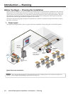
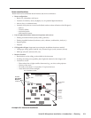
1. Room layout
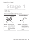
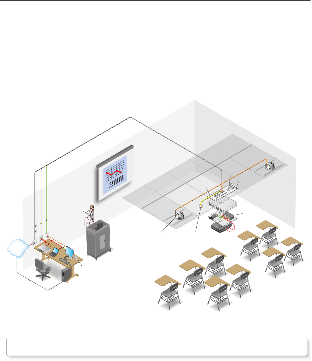
The application diagram below shows a typical classroom installation incorporating the VoiceLift Microphone.
PVS 204SA
PoleVault
Switcher
L
R
AUX/MIX IN
1B
1A
I
N
P
U
T
S
O
U
T
P
U
T
S
2B
2A
4
3
RS-232 MLC/IR
DC VOL
4/8
Ohms
AMPLIFIED OUTPUTS
VOL/MUTE
Tx
A
B
C
Rx
IR12V
10V
POWER
12V
3A MAX
US
LISTED
17TT
AUDIO/VIDEO
APPARATUS
®
RGB
VIDEO
RGB
VIDEO
STEREO
ON
DUAL
MONO
HIGH
PASS
FILTER
OFF
ON
Extron
PWR
CHARGE
OFF/MUTE/CHG
ON
Extron
CONFIG
DISPLAY
MLC 104 IP Plus
VOLUME
1
2
3
4
ON
OFF
VIDEO
AUX
VIDEO
IMAGE
MUTE
PC
COMPUTER IN
AUDIO IN
AUDIO IN
L
R
VIDEO IN
VLR 102
Receiver
VLC 102
Desktop Charging
Station
VLP 102
Pendant
Microphone
SI 3C LP
Plenum Full-Range
Ceiling Speakers
TCP/IP
Network
Typical classroom installation
N
Due to the operating frequencies of the microphone and receiver, lighting fixtures such as fluorescent lights and
plasma displays should not affect performance of the system.