


VoiceLift Microphone Installation • Reference Information
2-18
Reference Information
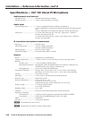
Audio
Tone control .................................... On or off, switch selectable
Audio input
Number/signal type
VLR 102............................... 1 infrared from VLM microphones
1 mono, balanced, aux/mix input
1 mono, balanced, from optional VLR 102SR
VLR 102SR .......................... 1 infrared from VLM microphones
1 mono, balanced, from optional VLR 102SR
Connectors
VLR 102............................... (1) 3.5 mm captive screw connector, 3 pole, for aux input
(1) RJ-45 female for input from a VLR 102SR
VLR 102SR .......................... (1) RJ-45 female for input from a VLR 102SR
N
0dBu=0.775Vrms,0dBV=1Vrms,0dBV≈2dBu
Audio output
Number/signal type ..................... 1 mono, balanced, line level
Connector ....................................... (1) RJ-45 female (shared with power input and some serial communication)
Pin configuration ........................... 1 = mic +, 2 = mic -, 3 = aux +, 6 = aux -, 8 = GND
Nominal level ................................ -10 dBV (316 mVrms)
IR sensor
Receiver type ................................. Superheterodyne IR sensor
Photodiodes ................................... 6, radially spaced
Receiving frequencies ................... 2.3 MHz, 2.8 MHz
Operating distance ........................ 40' (12.2 m) maximum, line-of sight, typical
Reception area ............................... 1600 square feet (148.6 square meters) per VLR 102
Reception angles ............................ 360° horizontal, 60° vertical
Control — host ports, VLR 102 only
Serial host port ............................... 1 RS-232, 3.5 mm captive screw connector, 3 pole
Baud rate and protocol ................. 38400 baud, 8 data bits, 1 stop bit, no parity
Serial control pin configuration .. 1 = TX, 2 = RX, 3 = GND
Control — relay output, VLR 102 only
Number/type ................................ 1 normally open
Connector ....................................... (1) 3.5 mm captive screw connector, 2 pole
Pin configuration ........................... NO = normally open, C = common
Contact rating ................................ 24 V, 1 A
Control — contact closure (VLR 102 only)
Number/type ................................ 1 contact closure input
Connector ....................................... (1) 3.5 mm captive screw connector, 2 pole
Pin configuration ........................... IN = contact input, GND = GND
Specications — VLR 102 and VLR 102 SR