


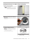
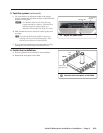
1. Connect the receiver to the
MLC 104 IP Plus.
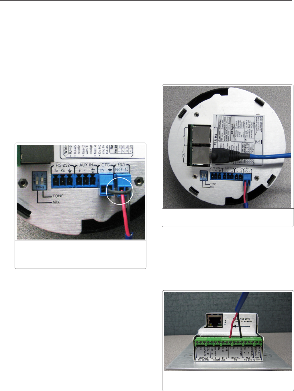
a. Wire one of the provided two-pole captive screw
connectors to one end of a communication cable.
b. Plug the communication cable into the receiver’s RLY
port.
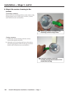
N
If the MLC controller and the PoleVault switcher
are using separate power supplies, ground the
Relayportcommonpintothereceiverusinga
jumper between the common pin and the ground
pinoneithertheContactinput,theAuxInput,or
theRS-232port.
c. Pull the communication cable to the MLC 104 IP Plus
location.
d. Connect the other end of the cable to a direct-insertion
Digital I/O port on the MLC:
• Insert the black wire into the Ground port.
• Insert the red wire into the rst available Digital I/O
port.
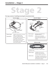
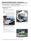
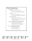
Installation Example — Setting Up an Instant Alert
The following pages describe an example of an optional instant alert setup, in which the relay port of the VLR 102
is connected to a digital I/O port of an Extron MLC 104 IP Plus. This enables e-mail alerts to be sent out when both
Volume buttons of the VLP 102 microphone are pressed and held for 3 seconds.
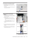
û
Connect the communication cable to
an MLC Digital I/O port.
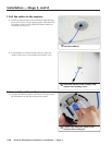
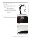
Å
Connect a communication cable to the
VLR 102 RLY port.
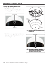
For separate power supplies, jumper-
connect the C pin of the Rly port to the
ground pin of the CTC, Aux In, or RS-232
port.
VoiceLift Microphone Installation • Optional Installation Example — Instant Alert
2-16
Optional Installation Example — Instant Alert