


4
Model VM08 Owner’s Manual
ST OUTR
L
PHONES
1
TRIM
2
TRIM
3
TRIM
4
TRIM
-10 -50
-10 -50
-10 -50
-10 -50
RESET
OUT
S/P DIF
DC IN
FOOT SW AUX SEND
INPUT
6/5
8/7
7
8
5
6
1
2
AD-9B
ONLY
9V
EQ
1
23
4
5
67
8
9
10 11 13
14
15
16
17
18
19
202122
23
24
25
26
27
28
12
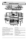
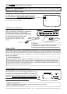
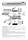
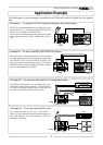
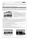
Names and Functions
1. AC adaptor connector
Connect the AC adaptor, included in the acces-
sory kit, to a wall AC socket and plug the adaptor
output cable to this jack (Be sure to use the adap-
tor included in the VM08 package).
2. S/P DIF optical output connector
The same signal output from the ST OUT L/R jack
is output here as digital audio signal in the S/P
DIF format.
3. Foot switch connecting jack
A foot switch (Fostex Model 8051) is plugged in
here. The foot switch function can be changed by
the [SETUP mode] explained later. The initial set-
ting recalls the scene memory. Refer to page 27
for details.
4. RESET switch
This switch resets the CPU inside VM08. Refer to
page 6 for details.
5. AUX send jack
AUX SEND level signals, adjusted in the channel
parameter edit mode, are output here. Refer to
pages 8 and 17 for details.
6. STEREO OUT L, R jack
The mixed signal is output to the MTR, stereo moni-
tor system or to other mixers. Output level is ad-
justed by the MASTER fader.
7. Headphone jack
The monitoring headphone is connected here.
Use the PHONES control to adjust the sound level.