


8
Model VM08 Owner’s Manual
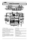
TRS Phone plug Phone plug
Music source side
VM08 side
VM08 side
VM08 side
VM08 side
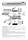
External Equipment
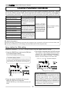
5) FOOT SW jack
This is an unbalanced type phone jack. An unlatch type foot switch (Fostex Model 8051) can be plugged in
here. Operations using the foot switch are selectable in the [Setup mode]. Refer to [Setup mode] on page
27 for details.
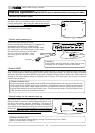
6) DC IN connector
Plug-in the tip of the power cord of the exclusive AC adaptor (AD-9B) here and plug the adaptor into a
household AC wall outlet. Since the VM08 does not have a power switch, ON/OFF of power is done by
plugging and unplugging the AC adaptor from the AC wall outlet. If you don’t plan on using the VM08 for
some length of time, the AC adaptor must be unplugged from the AC wall outlet.
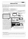
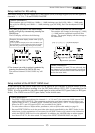
7) S/P DIF OUT connector
The same signals output from ST OUT L, R are output here as digital (S/P DIF) signals.
Signals mixed in an external digital master recorder connected here can be recorded in digital as shown in
the schematic. If external digital equipment to be connected is provided with only COAXIAL (RCA pin jack)
type IN/OUT connectors, use the optional Fostex COP-1/96k optical-coaxial converting adaptor sold sepa-
rately.
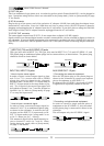
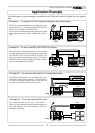
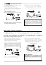
INPUT 5/6, INPUT 7/8 jacks:
* How to input a stereo signal:
In order to input a stereo output signal to chan-
nels 5/6 or 7/8, a stereo cable with a STEREO
phone plug wired as shown in the schematic
should be used. Set the INPUT 5/6 input mode or
INPUT 7/8 input mode in the setup mode to [Ste-
reo]. The L signal of the stereo input signal will
be applied to channel 5 (or 7) and the R signal to
channel 6 (or 8). Refer to [Setup mode] on page
27 to setup the input mode.
* How to input a monaural signal:
In order to input a monaural output signal to
channels 5/6 or 7/8, an unbalanced phone plug,
as shown in the schematic, is used for the con-
nection and the INPUT 5/6 input mode or IN-
PUT 7/8 input mode in the "setup mode" is set
to [In 5 > Mono] (or [In 7 > Mono]).
The monaural signal will be simultaneously in-
put to channels 5 and 6 (or 7 and 8). When
setting the input mode, refer to [Setup mode]
on page 27 for details.
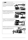
AUX SEND OUT 1/2 jack:
* Connecting two external equipment:
Wire the TRS phone plug to two phone plugs as
shown in the schematic to connect two separate
pieces of equipment to AUX SEND 1/2.
By doing so, the AUX SEND 1 signal and AUX SEND
2 signal will be separately output to the two.
* Connecting a single external equipment:
In order to connect a single external piece of
equipment to the AUX SEND 1/2 jack, the unbal-
anced phone plug is connected as shown in the
schematic.
This will output only the AUX SEND 1 signal.
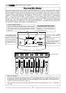
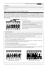
* INPUT 5/6 (7/8) and AUX SEND 1/2 jacks
TRS type jacks used at INPUT 5/6, TRS type jacks used at INPUT 5/6 (7/8) and AUX SEND 1/2, and
TRS phone plugs or unbalanced phone plugs can be connected here, as shown below. The phone plug
should be wired as shown below.
Music source side
External Equipment