


5
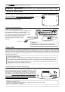
Model VM08 Owner’s Manual
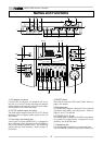
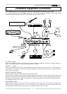
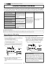
8. TRIM knob
Input gain is adjusted with this TRIM knob for each
sound source connected to input jacks 1 ~ 4.
The input level is adjustable over a wide range
from line level down to mic level.
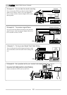
9. INPUT jacks
External sound sources are input here.
INPUTS 1 ~ 4 comply to mic/line and input gain
can be adjusted with the TRIM knob. INPUT's 5/6
and 7/8 are exclusively for line level signals.
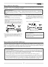
10. Contrast adjusting knob
The LCD display contrast is adjusted with this
knob.
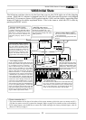
11. LCD display
Various figures are displayed here. Refer to [Ini-
tial state of VM08] in page 11 for details.
12. Scene number display
The current scene number is displayed here.
Refer to [Scene memory mode] on page 24 for de-
tails.
13. Status indicator
Using the channel parameter edit mode explained
later, what is currently setup can be confirmed by
the dot display. Items to be set can be selected
with the PAN/EQ key or the EFF/AUX key. Refer
to [Channel parameter edit mode] on page 14 for
details.
14. Scene Recall key
This is pressed to recall the scene memory ex-
plained later. Refer to [Recall of the scene memory]
on page 24 for details.
15. Scene Store key
This is pressed to store a scene memory. Refer to
[Storing the scene memory] on page 24 for de-
tails.
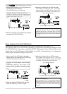
16. Effect 2 key
This is pressed to select the EFF 2 effects type or
the parameter to be edited. Also, if this key is
pressed while pressing the EXIT key, muting of EFF
2 can be switched ON/OFF. Refer to [Effect edit
mode] on page 18 for details.
17. Effect 1 key
This is pressed to select the EFF 1 effects type or
the parameter to be edited. Also, if this key is
pressed while pressing the EXIT key, muting of EFF
1 can be switched ON/OFF. Refer to [Effect edit
mode] on page 18 for details.
18. Enter key
This is used to accept the current mode setting.
This key will setup scene memory (page 24), the
setup mode (page 27) and also the setup of ef-
fects type (page 18). Please refer to their respec-
tive explanation for details.
19. Exit key
This is used to exit from all modes but the normal
mix mode. This key works for the channel param-
eter edit mode (page 14), the effects edit mode
20. Data encoder
This dial is rotated to make settings such as setup
of PAN and EQ. This dial works in the channel
parameter edit mode (page 14), the scene memory
mode (page 24) and the effects edit mode (page
18). Refer to their respective explanations for
details.
21. Master fader
This adjusts the master level of signal output from
the STEREO OUT L, R jacks and S/P DIF OUT.
22. Input fader
Signal levels of sound sources connected to each
INPUT jack can be adjusted with these faders. In-
put faders 5/6 and 7/8 controls both channels at
the same time.
23. EFF/AUX select key
The channel parameter edit mode is entered when
this key is pressed and EFFECT send output and
AUX send output can be adjusted. Refer to [Chan-
nel parameter edit mode] on page 14 for details.
24. PAN/EQ select key
The channel parameter edit mode is entered when
this key is pressed to setup of PAN and EQ. Refer
to [Channel parameter edit mode] on page 14 for
details.
25. Fader adjust key
This key warns by blinking if a fader position drifts
or sound volume is accidentally changed at switch
ON of power or at recall of the scene memory. Use
this key to enter the fader adjust mode to manu-
ally adjust the fader position. Refer to [Fader ad-
just mode] on page 25 for details.
26. Level adjust key
This key will blink together with of the FADER
ADJUST key. The level adjust mode is entered
when this key is pressed so the sound level can be
matched to the present fader position. Refer to
[Level adjust mode] on page 25 for details.
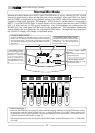
27. Channel On/Channel Select key
The channel to be edited can be selected while in
the channel parameter edit mode. In other modes,
channel ON/OFF is possible. Refer to [Normal mix
mode] on page 12 and [Channel parameter edit
mode] on page 14 for details.
28. Headphone volume
This adjusts the monitor headphone sound vol-
ume.
(page 18), the scene memory mode (page 24) and
the setup mode (page 27). Refer to their respec-
tive explanation for details.