


5 - 80
MELSEC-Q
5 DATA USED FOR POSITIONING CONTROL
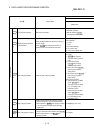
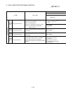
5.2.9 Servo parameters (Expansion setting)
Do not set other than the buffer memory addresses of the servo parameters in this section.
Item
2
Setting details
Setting value
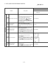
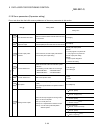
Pr.164
(PC01)
3
Error excessive alarm level
• Set error excessive alarm level with rotation amount
of servomotor.
1 to 200[rev]
Pr.165
(PC02)
Electromagnetic brake
sequence output
• Used to set the delay time between electronic brake
interlock (MBR) and the base drive circuit is shut-off.
0 to 1000[ms]
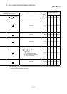
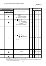
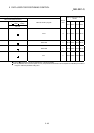
Pr.166
(PC03)
Encoder output pulses
selection
• Use to select the, encoder output pulse direction
and encoder pulse output setting.
Encoder pulse output phase
selection
0: CCW progress to A phases 90°
1: CW progress to A phases 90°
Encoder output pulse setting
selection
0: Output pulse designation
1: Division ratio setting
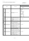
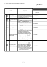
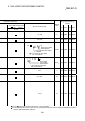
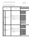
Pr.167
(PC04)
3
Function selection C-1
• Select the encoder cable communication system
selection.
The following encoder cables are four-wire type.
• MR-EKCBL30M-L • MR-EKCBL30M-H
• MR-EKCBL40M-H • MR-EKCBL50M-H
0: Two-wire type
1: Four-wire type
Pr.168
(PC05)
3
Function selection C-2 • Motor-less operation select.
0: Valid
1: Invalid
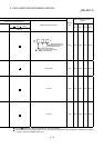
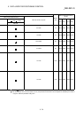
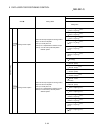
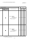
Pr.170
(PC07)
Zero speed
• Used to set the output range of the zero speed
(ZSP).
• Zero speed signal detection has hysterics width of
20[r/min].
0 to 10000[r/min]
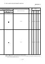
0: Servomotor speed
(
8V/max. speed)
1: Torque
(
8V/max. torque)
(Note-2)
2: Servomotor speed
(
+
8V/max. speed)
3: Torque
(
+
8V/max. torque)
(Note-2)
4: Current command
(
8V/max. current command)
5: Speed command
(
8V/max. speed)
Expansion setting
Pr.172
(PC09)
Analog monitor output 1
Used to set the output signal from analog monitor
output 1 of the servo amplifier.
(Note-1): Encoder pulse unit.
(Note-2): 8V is outputted at the maximum torque.
(Note-3): It can be used by absolute position
detection system.
6: Droop pulses
(
10V/1 x 10
2
[PLS])
(Note-1)