10 Pelco Manual C586M (9/99)
UNUSED
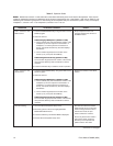
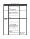
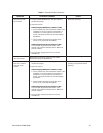
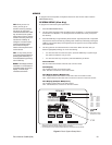
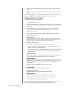
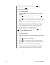
Switches 4 and 5 are not used in the multiplexer server mode. They must be placed in
the OFF position.
TURBO MODE
Set switch 6 ON to enable the turbo pan feature. Set the switch OFF to disable the
turbo pan feature.
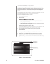
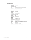
CAMERA ADDRESS MODE
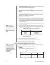
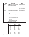
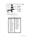
There are two modes for addressing cameras: by addressing all the cameras
consecutively from 1-256 (refer to Table D) or by addressing the cameras in groups of
16 according to the multiplexer they are connected to; for example, multiplexer 1,
cameras 1-16; multiplexer 2, cameras 1-16, etc.
Set switch 7 ON if you want to address all cameras consecutively.
Set switch 7 OFF if you want to address cameras according to the multiplexer they are
connected to.
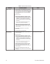
PROGRAMMING MODE
Set switch 8 ON to program the server and the multiplexer. Set the switch OFF to
disable programming.
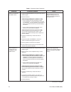
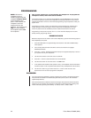
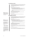
3. Replace the cover on the back of the keyboard.
4. Peel off the protective coverings over the LED display and the LCD monitor on the
keyboard.
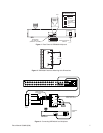
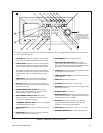
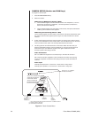
5. Attach the KBD4000V Interface to the wall with the screws that are provided (refer to
Figure 2). The interface must be within 6 feet (1.8 m) of the keyboard and the nearest
suitable electrical outlet. The interface cover can be removed for ease of mounting.
Replace the cover when the mounting is complete.
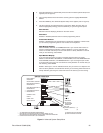
Refer to Figures 3-6 for the following steps.
6. Wire the interface to the server. Up to four keyboards can be connected to the server.
There are two methods:
a. One keyboard can be connected to the LOCAL KEYBOARD port and three to the
REMOTE KEYBOARD(S) port.
b. All four keyboards can be connected to the REMOTE KEYBOARD(S) port.
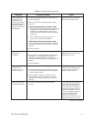
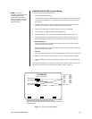
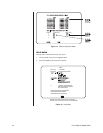
Refer to Figure 3 to wire the KBD4000V to the LOCAL KEYBOARD port of the
server. (NOTE: Figure 3 shows a multiplexer, not a server. Connect the 25-foot
(7.6 m) data cable from the wall block to the LOCAL KEYBOARD port on the
server, not to the COM IN connection on the multiplexer.)
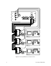
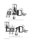
Refer to Figures 4-6 to wire the KBD4000V to the REMOTE KEYBOARD(S) port.
Figure 4 shows multiple KBD4000Vs connected to the server. Figures 5 and 6
show a single KBD4000V keyboard with KBD4000 or KBD4002 keyboards.
Maximum distance between the server and the farthest keyboard over 24-gauge
wire is 4,000 feet (1,219 m). Pelco recommends using shielded twisted pairs
cable, such as Belden 9843 or similar cable, that meets or exceeds the basic
requirements for RS-485 communication.
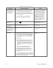
7. Connect a video coaxial cable from the VIDEO IN connector on the interface to a
VIDEO OUT connector on the rear of the server. Refer to Table A for the type of video
coaxial cable to use.
8. Connect the interface cable to the interface and keyboard.
9. Connect the +12 VDC power supply to the interface and source of power.
10. Turn on the power switch on the rear of the keyboard.
NOTE:
The 25-foot data
cable and the wall block
supplied with the keyboard
are not required when you
connect the keyboard to the
remote keyboard port of the
server.
NOTE:
If the distance
between the wall block and
interface exceeds the
maximum allowable coaxial
cable distance, use a video
amplifier to extend the
distance of the video coaxial
cable.