


6 Pelco Manual C586M (9/99)
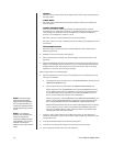
PROGRAMMING MODE
Set switch 8 ON to program the multiplexer and camera presets and patterns from the
keyboard. Set the switch OFF to disable programming.
3. Replace the cover on the back of the keyboard.
4. Peel off the protective coverings over the LED display and the LCD monitor on the
keyboard.
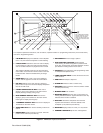
5. Attach the KBD4000V Interface to the wall with the screws that are provided (refer to
Figure 2). The interface must be within 6 feet (1.8 m) of the keyboard and the nearest
suitable electrical outlet. The interface cover can be removed for ease of mounting.
Replace the cover when the mounting is complete.
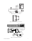
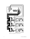
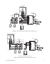
Refer to Figure 3 for the following steps.
6. Mount the wall block within 25 feet (7.6 m) of the multiplexer. Wire the wall block to the
interface. Maximum cable distance between the wall block and interface over 24-gauge
wire is 4,000 feet (1,219 m). Pelco recommends using shielded twisted pairs cable,
such as Belden 9843 or similar cable, that meets or exceeds the basic requirements
for RS-485 communication.
7. Connect the 25-foot (7.6 m) data cable to the wall block and to the COM IN port on the
rear panel of the multiplexer.
8. Connect a video coaxial cable from the VIDEO IN connector on the interface to the
MAIN or SPOT monitor connector on the rear panel of the multiplexer. Refer to Table A
for the type of video coaxial cable to use.
NOTE:
If the keyboard will
be connected to a server
that will operate in the
paired mode configuration,
only addresses 1 and 3 can
be used. Refer to the server
manual for information about
the paired mode
configuration.
9. Connect the interface cable to the interface and keyboard.
10. Connect the +12 VDC power supply to the interface and source of power.
11. Turn on the power switch on the rear of the keyboard.
MULTIPLEXER SERVER MODE INSTALLATION
1. Remove the DIP switch cover plate from the rear of the keyboard (refer to Figure 1).
2. Set the switches (refer to Figure 1 for switch locations).
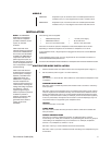
ADDRESS
Refer to Table B to set the address of the keyboard.
Table B. Keyboard Addresses
Keyboard Switch Settings
Address 1 2 3
1 ON OFF OFF
2 OFF ON OFF
3 ON ON OFF
4 OFF OFF ON
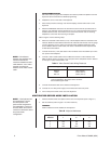
Table A. Video Coaxial Cable Wiring Distances
Cable Type* Maximum Distance
RG59/U 750 ft (229 m)
RG6/U 1,000 ft (305 m)
RG11/U 1,500 ft (457 m)
* Minimum cable requirements:
75 ohms impedance. All-copper center conductor.
95% braided copper shield.
NOTE:
If the distance
between the wall block and
interface exceeds the
maximum allowable coaxial
cable distance, use a video
amplifier to extend the
distance of the video coaxial
cable.