


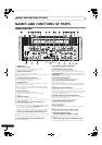

NAMES AND FUNCTIONS OF PARTS
8
En
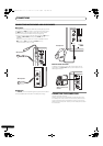
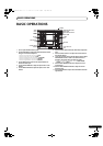
10 HEADPHONES output switch (MONO SPLIT/STEREO)
MONO SPLIT:
The source sound selected with the headphone CUE button is
output to the L channel, while the master sound is output to the R
channel (only when [MASTER] is selected with the headphone
CUE button).
STEREO:
The audio source selected with the headphone CUE button is
output in stereo.
11 HEADPHONES MIXING dial
When rotated clockwise (toward [MASTER]), the master output
audio is produced at the headphones (only when [MASTER] has
been selected with the headphone CUE button); when rotated
counterclockwise (toward [CUE]), the headphones output
becomes the mixture of the effect monitor and the channel
selected with the headphone CUE button.
12 HEADPHONES LEVEL adjust dial
Adjusts the output level of the headphones jack. (Adjustable
range: –∞ to 0 dB)
13 Headphones jack (PHONES)
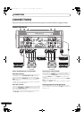
14 Channel 1 VIDEO INPUT selector switch
Set to [DVD], [VIDEO], [S-VIDEO], or [VIDEO EX] to match the
type of input connected.
15 Channel 2 VIDEO INPUT selector switch
Set to [DVD], [VIDEO], or [S-VIDEO] to match the type of input
connected.
16 Channel 3 VIDEO INPUT selector switch
Set to [DVD], [VIDEO], or [S-VIDEO] to match the type of input
connected.
17 Channel 4 VIDEO INPUT selector switch
Set to [DVD], [VIDEO], [S-VIDEO], or [VIDEO EX] to match the
type of input connected.
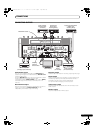
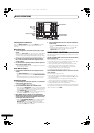
18 VIDEO TRIM dial
Use to adjust the level of the video input signal for each channel.
•When rotated counterclockwise, the luminance level is reduced,
eventually producing a black screen.
•When rotated clockwise, the luminance level is r aised,
eventually producing a white screen.
• At the center position, the luminance level is neutral (same level
as input).
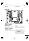
19 Channel 1 AUDIO INPUT selector switch
DVD/LINE:
Use to select DVD/LINE input connector s (line level analog input).
PHONO:
Use to select
PHONO input connector s (PHONO level analog
input).
20 Channel 2 AUDIO INPUT selector switch
DVD:
Use to select DVD input connectors.
LINE:
Use to select LINE input connectors (line level analog input).
DIGITAL:
Use to select DIGITAL input connector.
21 Channel 3 AUDIO INPUT selector switch
DVD:
Use to select DVD input connectors.
LINE:
Use to select LINE input connectors (line level analog input).
DIGITAL:
Use to select DIGITAL input connector.
22 Channel 4 AUDIO INPUT selector switch
DVD/LINE:
Use to select DVD/LINE input connector s (line level analog input).
PHONO:
Use to select PHONO input connectors (PHONO level analog
input).
23 AUDIO TRIM dial
Use to adjust the level of the audio input signal for each channel.
(Adjustable range: –∞ to +9 dB, mid-position is about 0 dB)
24 Channel equalizer high-range adjust dial (HI)
Use to adjust the treble (high-range) frequency sound for each
channel. Video parameters can also be assigned. See P. 34
regarding video parameters. (Adjustable range: –26 dB to +6 dB)
25 Channel equalizer mid-range adjust dial (MID)
Use to adjust the mid-range frequency sound for each channel.
Video parameters can also be assigned. See P. 34 regarding video
parameters. (Adjustable range: –26 dB to +6 dB)
26 Channel equalizer low-range adjust dial (LOW)
Use to adjust the bass (low-range) frequency sound for each
channel. Video parameters can also be assigned. See P. 34
regarding video parameters. (Adjustable range: –26 dB to +6 dB)
27 Channel level indicator
Displays the current level for each channel, with two-second peak
hold.
28 Headphone
CUE
buttons/indicators
These buttons are used to select from 1 to 4, MASTER, or
EFFECT CUE, to allow you to monitor the desired source through
headphones. If multiple buttons are pressed simultaneously, the
selected audio sources are mixed. Press the button once more to
cancel the selected source. Unselected buttons glow darkly, while
selected source buttons light brightly.
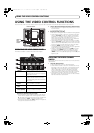
29 Channel fader lever
Use to adjust sound volumes and video level for each channel.
(Volume adjust range: –∞ to 0 dB) (Video adjust range: 0 % to
100 %)
Output is in accordance with the channel fader curve selected with
the CH FADER CURVE switch.
When FADER AV SYNC function is OFF, only sound volume can be
adjusted.
30 CROSS FADER ASSIGN switch
This switch assigns each channel’s output to either right or left
side of the cross fader (if multiple channels are assigned to the
same side, the result will be the combined sum of the channels).
A:
The selected channel is assigned to the cross fader’s [A] (left) side.
THRU:
The channel fader’s output is sent as is to the master output,
without being passed through the cross fader.
B:
The selected channel is assigned to the cross fader’s [B] (right)
side.
31 CROSS FADER CURVE switch
This switch allows the user to select from three types of cross fader
curve response.
Sound volume changes as follows:
• At the left setting, the curve produces a rapid signal rise. (As
soon as the cross fader lever leaves the [A] side, the [B] channel
sound is produced.)
• At the right setting, the curve operates to produce an even,
neutral rise throughout the cross fader’s movement.
• At the middle setting, an intermediate curve is produced,
midway between the two curves noted above.
The video level is as noted above only when the video cross fader’s
video mix effect is set to [FADE].
32 Video master output level dial (VIDEO MASTER LEVEL)
Adjusts the video master output luminance level.
33 Master output MONO/STEREO selector switch
When set to the [MONO] position, audio master output is
produced in L+R monaural.
34 Audio master output level dial (AUDIO MASTER LEVEL)
Use to adjust the master output level. (Adjustable range: –∞ to
0dB)
The master output is the sum combination of the sound from
channels set to [THRU] with the CROSS FADER ASSIGN switch;
the signal passed through the cross fader; and the signals from
microphone 1 and microphone 2.
SVM-1000_B_En.book 8 ページ 2007年11月26日 月曜日 午後12時54分