


59
Effects List
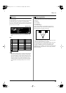
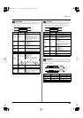
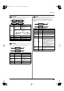
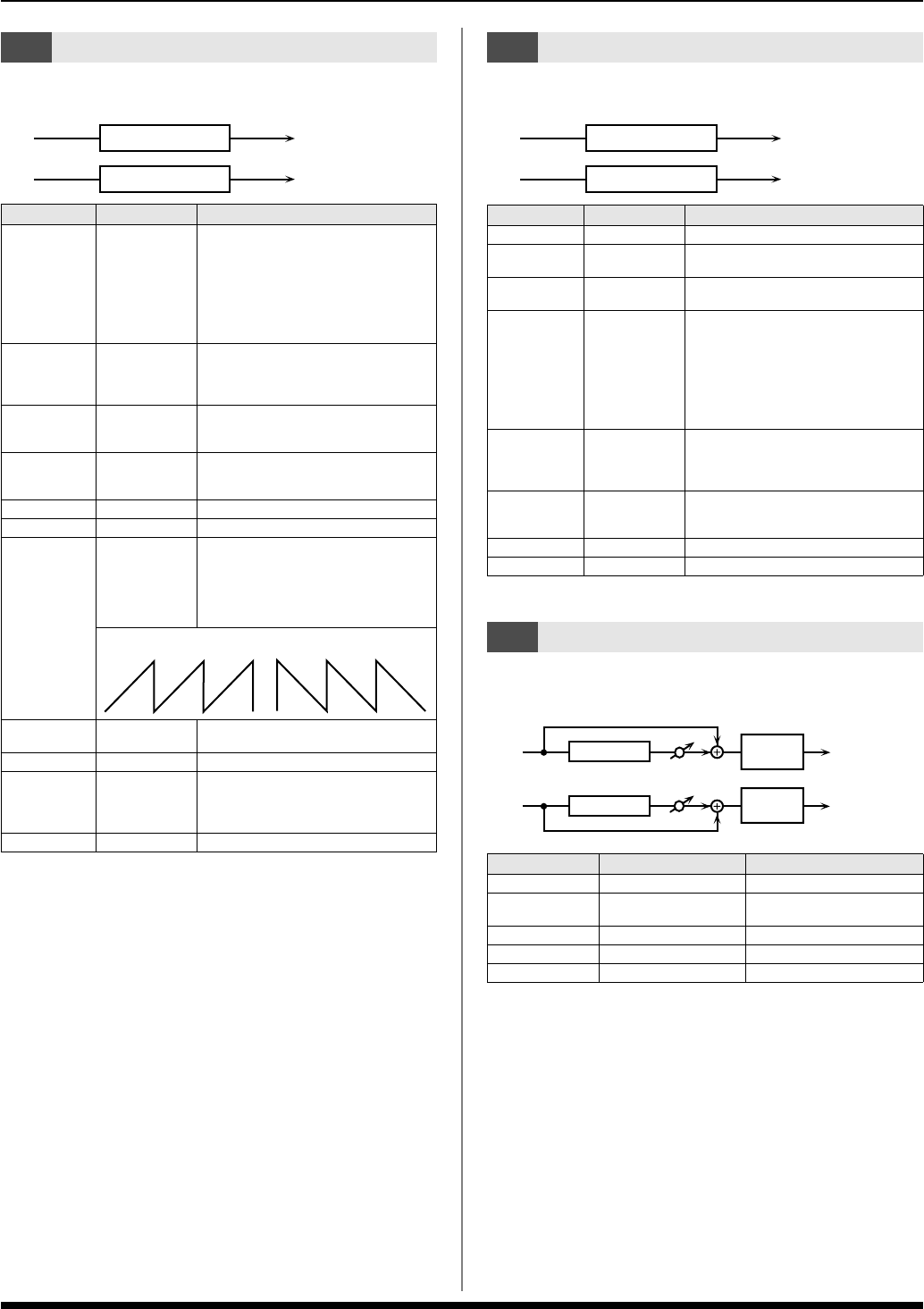
This is a filter with an extremely sharp slope. The cutoff frequency can
be varied cyclically.
fig.MFX-05
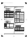
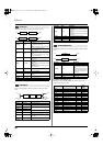
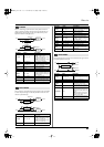
This is a filter whose cutoff frequency can be modulated in steps. You
can specify the pattern by which the cutoff frequency will change.
fig.MFX-06
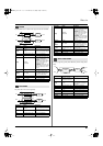
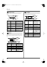
Controls the overtone structure of the high frequencies, adding sparkle
and tightness to the sound.
fig.MFX-07
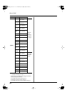
05: SUPER FILTER
Parameter
Value Description
Filter Type
LPF, BPF, HPF,
NOTCH
Filter type
Frequency range that will pass through
each filter
LPF:
frequencies below the cutoff
BPF:
frequencies in the region of the cutoff
HPF:
frequencies above the cutoff
NOTCH:
frequencies other than the re-
gion of the cutoff
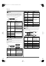
Filter Slope
-12, -24, -36 dB
Amount of attenuation per octave
-36 dB:
extremely steep
-24 dB:
steep
-12 dB:
gentle
Filter
Cutoff
0–127
Cutoff frequency of the filter
Increasing this value will raise the cutoff
frequency.
Filter
Resonance
0–127
Filter resonance level
Increasing this value will emphasize the
region near the cutoff frequency.
Filter Gain
0– +12 dB
Amount of boost for the filter output
Modulation Sw
OFF,ON
On/off switch for cyclic change
Modulation
Wave
TRI, SQR, SIN,
SAW1, SAW2
How the cutoff frequency will be modulated
TRI:
triangle wave
SQR:
square wave
SIN:
sine wave
SAW1:
sawtooth wave (upward)
SAW2:
sawtooth wave (downward)
Rate
0.05–10.00 Hz,
note
Rate of modulation
Depth
0–127
Depth of modulation
Attack
0–127
Speed at which the cutoff frequency will
change
This is effective if Modulation Wave is
SQR, SAW1, or SAW2.
Level
0–127
Output level
L in
R in
L out
R out
Super Filter
Super Filter
SAW1 SAW2
06: STEP FILTER
Parameter
Value Description
Step 01–16
0–127
Cutoff frequency at each step
Rate
0.05–10.00 Hz,
note
Rate of modulation
Attack
0–127
Speed at which the cutoff frequency
changes between steps
Filter Type
LPF, BPF, HPF,
NOTCH
Filter type
Frequency range that will pass through
each filter
LPF:
frequencies below the cutoff
BPF:
frequencies in the region of the cutoff
HPF:
frequencies above the cutoff
NOTCH:
frequencies other than the re-
gion of the cutoff
Filter Slope
-12, -24, -36 dB
Amount of attenuation per octave
-12 dB:
gentle
-24 dB:
steep
-36 dB:
extremely steep
Filter
Resonance
0–127
Filter resonance level
Increasing this value will emphasize the
region near the cutoff frequency.
Filter Gain
0– +12 dB Amount of boost for the filter output
Level
0–127 Output level
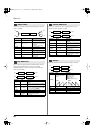
07: ENHANCER
Parameter Value Description
Sens
0–127
Sensitivity of the enhancer
Mix
0–127
Level of the overtones generat-
ed by the enhancer
Low Gain
-15– +15 dB Gain of the low range
High Gain
-15– +15 dB Gain of the high range
Level
0–127 Output Level
L in
R in
L out
R out
Step Filter
Step Filter
L in
R in
L out
R out
Mix
Mix
Enhancer
Enhancer
2-Band
EQ
2-Band
EQ
GW-8_e.book 59 ページ 2008年4月1日 火曜日 午前11時44分