


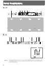

1 Pads 1–8
Play these pads to trigger the various sounds. The
pads are velocity sensitive and will respond to your
playing dynamics.
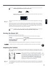
2 Patch display
This display indicates the Patch number or the value
of each parameter (p. 14).
3 PAD BANK indicator
Indicates the selected pad bank (A or B) (p. 16).
4 EFFECT indicator
The LED of the selected effect will light (p. 28).
5 Parameter List
In the Edit mode, the indicator of the selected para-
meter will light (p. 20). Use the [SELECT] (Parameter
Group Select) and [ ][ ] (Parameter Select) but-
tons to choose parameters (p. 21).
6
Parameter Group Select button [SELECT]
In the Edit mode, this button selects the desired para-
meter group: SOUND, MIDI, FX/PEDAL, or SYS-
TEM (p. 21).
7 Parameter Select buttons [ ][ ]
In the Edit mode, use these buttons to select a para-
meter within the parameter group (p. 21).
8 [PATCH CHAIN] button
Use this button when setting up or playing a Patch
Chain (p. 33).
9 [BANK A/B] button
Switches you between pad banks A and B
(p. 16).
10 [COPY] button
Use to copy data from one Patch to another (p. 32).
11 [LAYER] button
This button allows the sounds assigned to pad banks
A and B to be played together (p. 15).
12 [EDIT] button
This button switches between the Edit and Play
modes (p. 19).
13 [FX ON/OFF] button
This button turns the effects on or off (p. 28).
14 [ALL/ENTER] button
Use this button when setting all pads to the same
value (p. 27), when performing a copy (p. 32), or
when storing Patch Chain settings (p. 33).
15 PATCH/VALUE [-], [+] buttons
These buttons are used to select Patches. In the Edit
mode they are used to modify parameter values
(p. 14).
16 VOLUME knob
Adjusts the volume of the OUTPUT jacks and
PHONES jack (p. 13).
17 PHONES jack
A pair of stereo headphones can be connected to this
jack. Even with headphones connected, the OUTPUT
jacks will still be active (p. 12).
18 OUTPUT (R, L/MONO) jacks
These jacks output the sound of the SPD-20. For
monaural output use the L/MONO jack (p. 12).
19 [HH CTRL/TRIG 4] select switch
If a hi-hat control pedal (FD-7; sold separately) is con-
nected to the hi-hat control pedal jack, set this switch
to HH CTRL (p. 40). If an external pad is connected,
set this switch to TRIG 4 (p. 37).
20 HH CTRL/TRIG 4 jack
A hi-hat control pedal (FD-7; sold separately) can be
connected to this jack. If the external input select
switch is set to TRIG 4, an external pad can be con-
nected to this jack (p. 35, 36).
21. TRIGGER INPUT 1–3 jacks
External pads etc. can be connected here (p. 37).
Use Trigger Input jack 1 and 2 to allow the play-
ing of rim shots when using a PD-120 pad (p. 38).
22. MIDI IN/OUT connectors
External MIDI devices can be connected here (p. 57).
23. FOOT SW jack
A footswitch can be connected here allowing you to
change Patches by remote control. If you use a special
cable (PCS-31; sold separately) to connect two FS-5U
switches (sold separately), you can move up or down
through the Patch numbers. If you connect a DP-2
switch (sold separately), you can move up (but not
down) through the Patch numbers (p. 15).
24. AC adaptor jack
Connect the included AC adaptor here (p. 12).
Use only the included AC
adaptor. Use of any other AC
adaptor may cause damage or
malfunction.
25. POWER switch
This switch turns the unit on/off (p. 12).
MEMO
9
1
2
3
4
5