


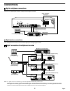
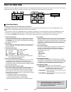
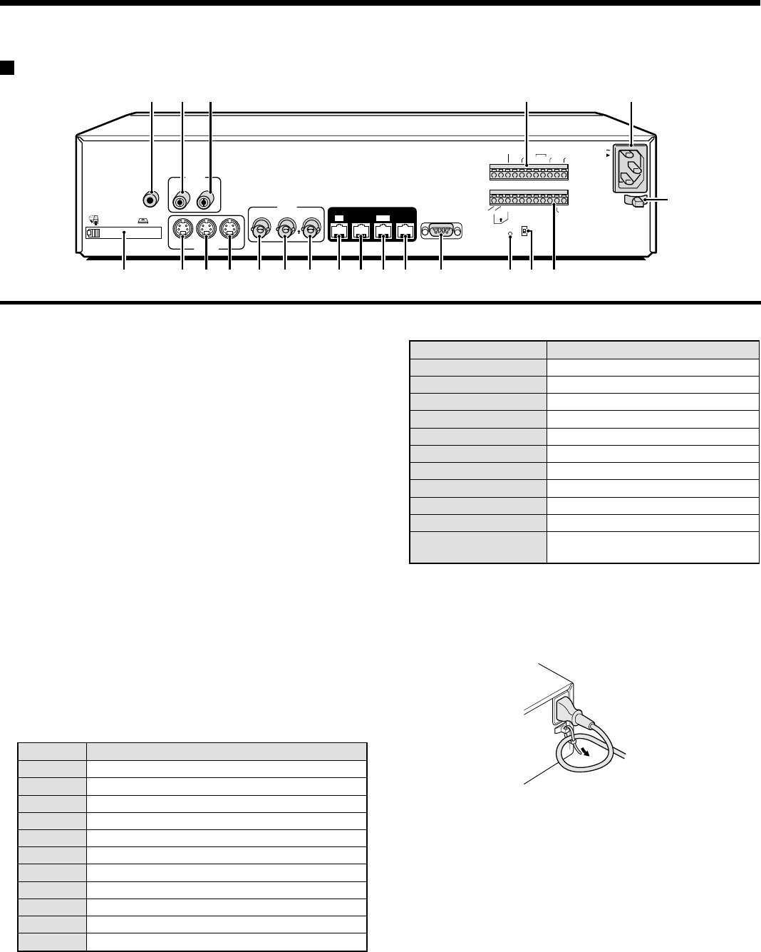
PART NAMES
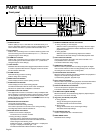
Rear panel
1
PC card slot
Connect a recommended network card or SCSI card here.
Note: The PC card slot is for 16 bit 5 V cards only.
Do not use 32 bit card bus types of card, as they may damage
the PC card slot of the digital video recorder.
2
MIC IN terminal
3
AUDIO IN terminal
4
AUDIO OUT terminal
5
S-VIDEO IN terminal
6
S-VIDEO LOOP OUT terminal
7
S-VIDEO OUT terminal
8
VIDEO IN terminal
Images being input to the S-VIDEO IN terminal take priority.
9
VIDEO LOOP OUT terminal
F
VIDEO OUT terminal
G
DIGITAL VIDEO IN terminal
H
DIGITAL VIDEO OUT terminal
I
DIGITAL VIDEO SUB IN terminal
J
DIGITAL VIDEO SUB OUT terminal
K
RS-232C terminal
L
ALL RESET button
M
RS-485 termination switch
N
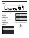
Control connector
Pin Signal
C Ground
A RS-485 connector*
B RS-485 connector*
C Ground
REMOTE Remote control input
C Ground
NC Spare
NC Spare
C Ground
SW OUT Switching output
C Ground
* Used for twisted-pair cable connection.
O
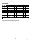
Alarm connector
Pin Signal
C Ground
ALARM IN Alarm input
ALARM RESET Alarm reset input
ALARM OUT Alarm output
NON REC OUT Non-rec output
C Ground
CLOCK ADJUST IN Clock sync input (See page 43.)
CLOCK ADJUST OUT Clock sync output (See page 43.)
WARNING OUT HDD error warning output
FULL HDD space warning output
ALARM OUT Alarm recording area space warning
output
P
AC power socket (AC IN~)
Securely insert the accessory power cord here.
Q
Power cord holder
Secure the power cord to the holder using the accessory cord tie as
shown in the illustration.
AC IN
RS232C
ALARM
FULL
SW OUT
WARNING
OUT
FULLOUTIN
ALARM
OUT
CLOCK
ADJUST
C
CCNC
C
NON REC
OUT
ALARM
IN
ALARM
RESET
NCCC
OFF
ALL
RESET
RS485
TERMINATE
B
A
ON
C
RS485
REMOTE
SUB OUT
OUT
DIGITAL
VIDEO
AUDIO
S-VIDEO
SUB IN
IN
OUT
OUT
LOOP OUT
LOOP OUT
IN
OUTIN
MIC
IN
IN
EJECT
PC Card SLOT
234 O P
NMLKJIHGF987651
Q
6
English