


TAC AB, 2003-07-01 0-004-7771-2 (GB), 13 (36)
TAC Xenta 400 I/O modules 3 Technical description
3 Technical description
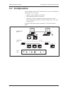
3.1 Common features
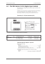
3.1.1 Terminals
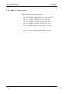
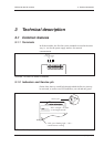
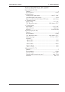
In all the modules, the first four screw terminals are used in the same
way, i.e. two for the power supply and two for network
communication.
~ 0
24 V AC
(19-40 V DC)
}
1 2 3 4 5 6 7 8 9 10
G G0 C1C2
Comm
}
Terminals 1-4 of the TAC Xenta I/O modules
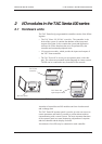
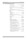
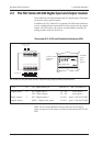
3.1.2 Indicators and Service pin
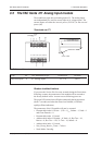
On the front, there is a small hole through which the Service pin may
be activated, as well as two LED indicators, one red and one green.
LEDs and Service pin of the I/O modules
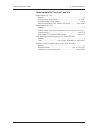
LED: green blinking light, ~1 Hz =
communication running
LED: red light = hw fault
or unconfigured node
Service pin: